
Motor controllers for electric vehicles and industrial machinery rely on a precise set of parameters to operate correctly. Adjust the wrong value, and you risk poor performance, overheating, or damage to the motor. Most modern controllers are configured through PC-based software, but the question comes up regularly: is it possible to tune a motor controller without connecting a computer at all? The short answer is yes, in limited circumstances, though the scope of what can be achieved through manual motor controller tuning is narrower than many assume.
Understanding where manual adjustment is genuinely useful, and where it runs into hard limits, helps technicians make better decisions in the field and avoid the frustration of chasing problems with inadequate tools.
What manual tuning actually involves
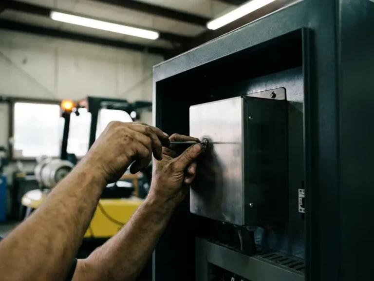
Manual tuning refers to adjusting controller parameters without using dedicated configuration software running on a PC or laptop. In practice, this usually means interacting directly with the hardware through physical interfaces built into the controller itself, or by manipulating input signals to observe system responses.
The parameters most commonly targeted through manual methods include throttle response curves, acceleration and deceleration ramp rates, and current limits. These are settings that affect how the vehicle or machine behaves in operation, and small changes can produce noticeable differences in feel and performance. Motor-specific parameters, such as flux settings for AC induction motors or inductance values for PMAC motors, are a different matter entirely and typically cannot be set reliably without software.
Hardware interfaces used for PC-free tuning
Some controllers include onboard adjustment mechanisms that allow basic parameter changes without any external computing device. These range from physical potentiometers and DIP switches to simple push-button interfaces with LED feedback. Each approach gives access to a narrow slice of the full parameter set.
Potentiometers are the most traditional method. Turning a trimmer pot adjusts a single mapped value, such as maximum current or speed limit, within a fixed range. DIP switches work similarly, selecting from predefined configuration profiles rather than allowing continuous adjustment. More sophisticated controllers may include a small display and button interface that lets the technician scroll through a limited menu of parameters and change values numerically, without any PC involved.
CAN bus or serial interfaces are also worth mentioning here. Some controllers expose a subset of parameters through a handheld diagnostic tool rather than a full PC application. These tools connect directly to the controller and provide a more structured tuning experience than potentiometers, though they still offer less flexibility than full software access.
Where manual tuning falls short
The most significant limitation of manual motor controller tuning is the inability to configure motor-specific electrical parameters. AC induction motors and PMAC motors require values such as stator resistance, rotor time constant, and flux current settings to be matched accurately to the physical motor. Getting these wrong does not just reduce efficiency; it can cause instability, excessive heat, or motor damage under load.
Beyond motor parameters, manual methods typically cannot access protection thresholds, sensor calibration routines, or multi-motor coordination settings. If the application involves dual traction motors, pump control, or power steering, the interaction between those outputs almost always requires software to configure correctly. Physical interfaces simply do not expose enough of the parameter space to handle that level of complexity.
There is also the question of repeatability. Potentiometer-based adjustments are inherently imprecise and can drift over time or with temperature. Documenting a configuration for future reference is difficult when there is no digital record of the values set.
Automated tuning as an alternative to manual adjustment
For the parameters that matter most to motor performance, automated tuning routines offer a far more reliable path than manual adjustment. Rather than requiring the technician to know and enter the correct motor electrical parameters, an automated routine runs a series of controlled tests, measures the motor’s actual response, and calculates the correct settings from the results.
This approach removes the need for detailed motor datasheets and eliminates the trial-and-error process that manual tuning would otherwise require. It is particularly valuable when working with motors where documentation is incomplete or when a replacement motor has slightly different characteristics from the original. Automated routines can also handle sensor calibration, confirming that encoder or resolver feedback aligns correctly with the motor’s physical position.
The trade-off is that automated tuning typically does require a PC connection to initiate and monitor the routine, at least for the initial commissioning. Once complete, the calibrated values are stored in the controller, and the system can operate independently.
When a PC connection is worth the extra step
For anything beyond basic operational adjustments, connecting a PC is almost always the right choice. The visibility alone justifies the effort: software interfaces display live data from the controller, including motor current, temperature, speed feedback, and fault codes, while changes are being made. That real-time feedback makes it possible to confirm that a parameter change has had the intended effect rather than guessing based on vehicle behavior.
PC-based configuration also allows full access to protection settings, which are easy to overlook during manual tuning but critical for long-term reliability. Overcurrent limits, thermal cutback thresholds, and undervoltage protection all need to be set appropriately for the specific application and battery system. Leaving these at default values, or being unable to access them at all, creates a risk that only becomes apparent when something goes wrong.
For initial commissioning of any electric vehicle controller, a PC connection should be treated as standard practice rather than an optional extra.
How DMC helps with motor controller tuning
DMC’s SuperSigma2 and Sigma2N controller ranges are designed to make the tuning process as straightforward as possible, whether the application involves AC induction or PMAC motors operating across a wide voltage range. Key features that directly address the challenges discussed above include:
- Fully automated motor and sensor tuning routines that calculate correct parameters from measured motor response, removing the need for manual entry of electrical values
- Sensorless motor control capability for applications where encoder or resolver feedback is unavailable or impractical
- Support for single and dual motor configurations, including traction, pump, and power steering outputs, all configurable through a unified software interface
- IMS-based thermal design that keeps power devices cooler, reducing the sensitivity of the system to parameter errors during setup
For applications ranging from forklifts and AGVs to marine platforms and hybrid vehicles, DMC’s controllers are built to be commissioned efficiently and reliably. To discuss a specific application or get support with controller configuration, contact the DMC team directly.
Related Articles
- How do CANopen and J1939 differ in handling vehicle communication?
- How does vehicle weight influence electric steering demand?
- What makes the SuperSigma2 different from earlier DMC controller ranges?
- BLDC vs PMSM controllers: are they the same thing?
- What's different about a series-wound motor controller compared to AC or PMS?