
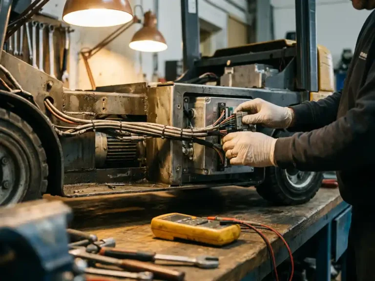
Commissioning a motor controller has never been a trivial task. Between characterising the motor, calibrating sensors, and validating performance under load, a skilled engineer can spend hours on a single installation before the vehicle even moves. As electric vehicle fleets and industrial platforms grow more complex, that time cost compounds quickly. Automated motor tuning changes the equation by replacing a sequence of manual measurements with a structured, software-driven process that the controller runs itself.
For field service engineers working across AGVs, forklifts, scissor-lifts, and similar platforms, the practical question is straightforward: how much does autotuning actually reduce commissioning time, and where does it make the biggest difference? The answer depends on understanding what manual commissioning required in the first place.
Need a controller for your application?
From traction to pump control, ask us about the right solution for your requirements.
Manual commissioning: the bottleneck autotuning replaces
Traditional motor controller commissioning required an engineer to measure or manually enter a range of motor parameters before the controller could operate correctly. Stator resistance, rotor time constant, inductance values, encoder offset, and Hall sensor alignment all needed to be determined, often through separate test routines or extracted from motor datasheets that did not always reflect the actual unit installed.
The problem with datasheet-based setup is that real-world motors vary. Manufacturing tolerances, cable lengths, connector resistance, and ambient temperature all shift the actual electrical characteristics away from nominal values. An engineer relying on published figures would frequently need to iterate, adjusting parameters after observing poor torque response or instability, then repeating load tests until performance stabilised. On a busy workshop floor with multiple vehicles to commission, that iterative loop became the primary bottleneck in getting equipment back into service.
Sensor calibration added another layer of complexity. Encoder phasing errors and Hall sensor misalignment are among the most common sources of erratic startup behaviour, and diagnosing them manually required oscilloscope access and a methodical process of elimination. Autotuning replaces that process entirely.
How automated motor and sensor tuning works
When a controller runs an automated tuning sequence, it applies controlled test signals to the motor windings and measures the electrical response directly. From those measurements, it derives the motor’s actual resistance, inductance, and time constants, building an accurate model of the specific unit connected rather than relying on generalised figures.
Sensor tuning follows a similar principle. The controller rotates the motor through a defined sequence and reads the feedback signals from the encoder or Hall sensors in real time. It identifies the correct phase alignment automatically and stores the offset values without any manual input from the engineer. The entire sequence typically completes in under a minute.
What makes this approach reliable is that it measures the complete system, not just the motor in isolation. Cable resistance, connector quality, and any impedance introduced by the installation are captured in the measurements and factored into the resulting parameter set. The controller is therefore tuned to the actual installation, not to a theoretical one.
Time savings across common EV and industrial applications
The time reduction autotuning delivers is most visible in applications where motors are replaced or swapped frequently. In forklift and stacker fleets, motors are consumable components that are changed during scheduled maintenance. Without autotuning, each replacement triggered a full manual commissioning cycle. With automated tuning, the engineer connects the replacement motor, initiates the tuning sequence, and the controller adapts to the new unit within minutes.
AGV platforms present a different scenario. These vehicles often run in large numbers across a single facility, and consistent performance across the fleet matters as much as individual commissioning speed. Autotuning removes technician-to-technician variability from the process. Every vehicle is tuned to the same standard because the measurement process is identical regardless of who initiates it.
Boom and scissor-lifts add the complication of pump and power-steering motors alongside the traction drive. Platforms that require multiple motor controllers to be commissioned in a single session benefit disproportionately from autotuning, since the time saving multiplies across each motor in the system.
Sensorless control and its impact on installation complexity
Sensorless motor control eliminates the encoder or Hall sensor hardware entirely, which removes a significant source of installation complexity. Without physical sensors to mount, align, and wire, the installation footprint shrinks and the number of potential failure points decreases.
In sensorless operation, the controller derives rotor position from the motor’s back-EMF and electrical characteristics rather than from a dedicated feedback device. This works well in applications where the motor operates above a minimum speed threshold for most of its duty cycle, such as pump drives and auxiliary functions.
For traction applications, the picture is more nuanced. Sensorless control performs well at running speeds but can struggle with the precise torque control needed at very low speeds and standstill, which are conditions that traction motors encounter constantly during manoeuvring and inching. This is why many engineers working on traction motor controllers retain physical sensors for drive axles even when sensorless modes are available, reserving sensorless operation for non-traction motors where the speed profile is more predictable.
Common commissioning errors that autotuning eliminates
Several recurring errors in manual commissioning stem directly from the reliance on entered parameters rather than measured ones. Incorrect stator resistance values lead to poor current regulation, which shows up as sluggish acceleration or excessive motor heating under load. Entering the wrong rotor time constant degrades field-oriented control accuracy, reducing efficiency and torque linearity across the speed range.
Sensor-related errors are equally common. A Hall sensor offset entered incorrectly by even a few degrees can cause rough startup, audible noise at low speeds, or a tendency for the motor to momentarily reverse before moving in the commanded direction. These symptoms are often misdiagnosed as mechanical problems, leading to unnecessary disassembly before the electrical cause is identified.
Autotuning removes the opportunity for these errors because there are no parameters to enter manually. The controller measures what it needs, stores the values, and applies them consistently. Engineers still need to verify that the motor is correctly wired and that the mechanical installation is sound, but the parameter-related errors that consumed diagnostic time in manual commissioning are no longer part of the process.
How the SuperSigma2 helps with motor controller commissioning
DMC’s SuperSigma2 range was designed with commissioning efficiency as a core requirement, not an afterthought. The platform supports AC induction, PMS, and IPM motors across a single hardware range, operating from 24V to 108V with nominal power up to 30 kW and peak power up to 60 kW. Fully automated motor and sensor tuning is standard across the range, covering all three motor types without requiring different tooling or procedures for each.
- Automated tuning sequences measure the actual installed motor and sensor characteristics, eliminating manual parameter entry for resistance, inductance, and sensor offset values.
- Sensorless control is available for pump and auxiliary motor applications, reducing sensor hardware and wiring on non-traction drives.
- The IMS (Insulated Metal Substrate) power stage keeps switching devices cooler than conventional PCB designs, maintaining reliable operation across demanding duty cycles without derating.
- CANopen connectivity supports fleet-level diagnostics and parameter management, which is particularly useful when commissioning multiple vehicles to a consistent standard.
For engineers responsible for commissioning and maintaining battery-driven vehicles and industrial platforms, the SuperSigma2 reduces the time from installation to verified operation. To discuss specific application requirements or get technical support for an existing installation, contact the DMC team directly.
Related Articles
- What happens if you run a motor in field weakening for too long?
- How big of a battery do I need to run a 3000W inverter?
- How does vehicle layout influence single-motor versus dual-motor traction architecture?
- Is IPM the same as PMSM? Here's the real difference
- Is vector control necessary for electric vehicle drivetrains?