
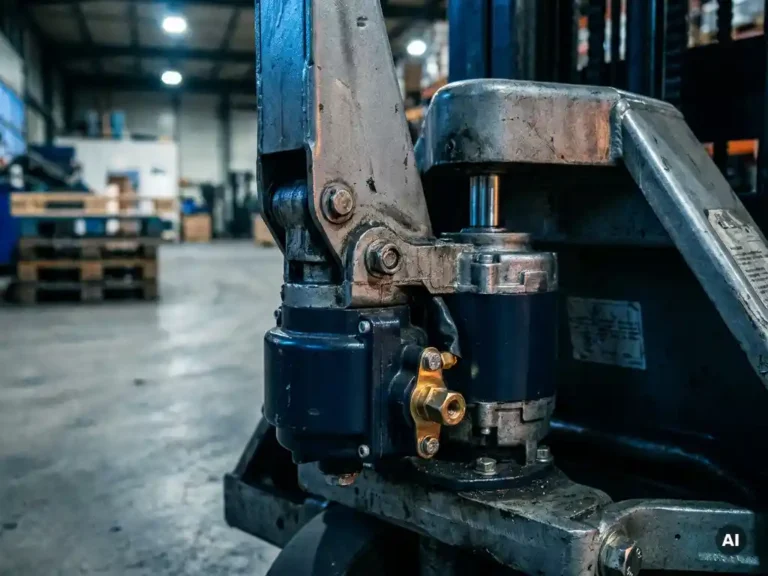
Electric power steering in industrial vehicles works by using an electric motor to apply torque directly to the steering column or rack, reducing the physical effort a driver needs to turn the wheels. The motor is controlled by an electronic control unit that reads steering inputs and vehicle conditions in real time, then calculates the appropriate level of assistance. The sections below address the most common technical questions about how these systems are designed, controlled, and maintained.
What components make up an electric power steering system?
An electric power steering system consists of a torque sensor, an electronic control unit (ECU), an electric motor, and a mechanical linkage that connects motor output to the steering mechanism. These four elements work together to detect driver input, compute the required assistance, and deliver it precisely to the steering column or rack.
The torque sensor sits at the steering column and measures how much force the driver is applying to the wheel. This signal is the primary input to the ECU, which also receives data from wheel speed sensors, vehicle load indicators, and sometimes a steering angle sensor. The ECU processes all of this to determine how much motor torque to apply and in which direction.
The electric motor itself is typically a compact AC or brushless DC unit mounted either on the column (column-assist EPS) or directly on the rack (rack-assist EPS). In industrial vehicles such as forklifts and stackers, column-assist configurations are common because they integrate more easily into existing vehicle architectures. The motor drives through a reduction gear or worm drive, multiplying its output torque before it reaches the steering linkage.
How does the controller decide how much steering assistance to give?
The controller uses a real-time algorithm that weighs torque sensor data against vehicle speed, load, and sometimes battery voltage to calculate an assistance level. At low speeds and high loads, the algorithm commands more motor torque; at higher speeds, it reduces assistance to preserve steering feel and directional stability.
This logic is sometimes called a speed-dependent assist curve. The ECU maps torque sensor input to a target motor current, and the motor controller then regulates current delivery to match that target. In practice, the controller is running a closed-loop current control loop at frequencies well above what a human operator can perceive, which is why EPS assistance feels smooth rather than stepped.
In industrial vehicles, the assist curve is often calibrated for the specific duty cycle of the platform. A reach truck operating in a narrow aisle has different steering demands than a tow tractor on an open floor, and the ECU parameters are tuned accordingly during commissioning. Some systems also adjust assistance based on battery state of charge, reducing motor load when the battery is low to extend runtime.
How does electric power steering differ from hydraulic power steering in industrial vehicles?
Hydraulic power steering uses a pump driven continuously by the vehicle’s drivetrain or a dedicated motor to pressurize fluid, which then actuates a hydraulic cylinder at the steering gear. Electric power steering replaces the hydraulic circuit entirely with an electric motor and electronic controller, consuming energy only when steering input is detected.
The practical differences for industrial vehicle operators and OEM engineers are significant. Hydraulic systems require regular fluid checks, hose inspections, and pump maintenance. EPS eliminates the hydraulic circuit, reducing the number of service points and the risk of fluid leaks, which matters in food processing, cleanroom, and indoor warehouse environments.
Energy consumption is another meaningful difference. A hydraulic pump runs continuously regardless of whether the operator is turning the wheel, drawing constant power. An EPS motor draws current only on demand, which reduces overall energy use and can extend battery range in electric vehicles. For AGVs and electric forklifts, where runtime per charge is a key performance metric, this is a genuine engineering advantage.
The trade-off is that EPS performance depends entirely on the electronics remaining functional. A hydraulic system can sometimes provide reduced steering capability even with a partial electrical fault, whereas EPS systems typically fail to a locked or unassisted state when the ECU or motor controller detects a fault condition.
What motor types are used in industrial EPS systems?
Industrial electric power steering systems predominantly use permanent magnet synchronous motors (PMSM) or brushless DC motors (BLDC). Both offer high torque density in a compact package, precise torque control, and low maintenance compared to brushed DC motors, which were common in earlier EPS designs.
PMSM motors are well suited to EPS because they deliver smooth, controllable torque across a wide speed range, and their efficiency at low speeds matches the operating profile of a steering motor, which often works at near-zero speed under high load. AC induction motors appear less frequently in EPS applications because their torque control at very low speeds is more demanding, though modern vector control techniques have made them viable in some industrial platforms.
The motor type directly influences the controller architecture required. PMSM and BLDC motors need rotor position feedback for commutation, which is typically provided by a resolver or encoder. This position data also feeds the torque control loop, so the quality of the sensor directly affects steering feel and assist accuracy.
What are the main failure modes in electric power steering systems?
The most common failure modes in industrial EPS systems are torque sensor faults, motor controller faults, motor winding degradation, and mechanical wear in the reduction gear. Each produces a distinct symptom that experienced field technicians can identify through a combination of fault codes and physical inspection.
Torque sensor failures often appear as erratic or absent assist, sometimes with the steering pulling to one side. Because the ECU relies on the torque sensor as its primary input, a corrupted or missing signal typically triggers a fault state and disables assistance entirely as a safety measure. Connector corrosion and mechanical damage to the sensor body are the most frequent root causes in industrial environments.
Motor controller faults can result from overtemperature, overcurrent, or communication errors. Industrial EPS controllers are exposed to vibration, contamination, and wide temperature swings, all of which stress solder joints, connectors, and power components over time. Thermal management at the controller level is therefore a meaningful reliability factor, not just a performance consideration.
Mechanical wear in the worm drive or reduction gear produces a characteristic looseness or play in the steering that progressively worsens. This is distinct from an electrical fault and requires physical inspection rather than fault-code analysis to confirm.
Can a standard motor controller be used for power steering applications?
A general-purpose motor controller can drive the motor in an EPS system, but a standard traction controller is not a direct substitute for a purpose-configured steering controller without careful engineering consideration. EPS applications have specific requirements around torque response speed, safety behavior on fault, and integration with the vehicle’s steering angle and torque sensors that a generic controller may not meet out of the box.
The key difference is the control loop priority. In traction, the controller manages speed and torque over a relatively long time horizon. In steering, the controller must respond to torque sensor commands in milliseconds to maintain natural steering feel. A controller with insufficient bandwidth or a software architecture not designed for steering assist will produce sluggish or inconsistent response.
Safety behavior on fault is equally important. An EPS controller must fail in a defined, safe state, typically by disabling assist and allowing manual steering, rather than holding a last-known torque command. This requires explicit fault handling logic in the firmware, not just hardware protection.
For OEM engineers evaluating whether an existing motor controller platform can support a power steering motor, the questions to ask are: Can the controller run a sufficiently fast current control loop? Does it support the sensor interface required by the steering motor? And does its fault response logic meet the safety requirements of the application?
How the SuperSigma2 supports power steering motor control
DMC’s SuperSigma2 controller is designed to drive pump and power steering motors alongside traction applications, making it a practical option for OEM engineers who want a single controller platform across multiple vehicle functions. Relevant capabilities for power steering use include:
- Support for AC induction, PMSM, and IPM motor types, covering the motor technologies most commonly used in industrial EPS systems
- Fully automated motor and sensor tuning, which reduces commissioning time when integrating the controller with a new steering motor and sensor combination
- Nominal operating range from 24 V to 108 V, matching the battery voltages used across AGVs, forklifts, stackers, and similar industrial platforms
- Dual-processor architecture with CANopen support, enabling the controller to receive steering demand signals from the vehicle’s main ECU over a standard fieldbus
- IMS (Insulated Metal Substrate) thermal management, which keeps power switching devices cooler under the sustained low-speed, high-current loads typical of steering motor applications
For engineers specifying a motor controller for a power steering or pump motor application, the SuperSigma2 is worth evaluating as a configurable platform rather than a fixed steering controller. To discuss whether it fits your specific application, contact the DMC engineering team directly.