
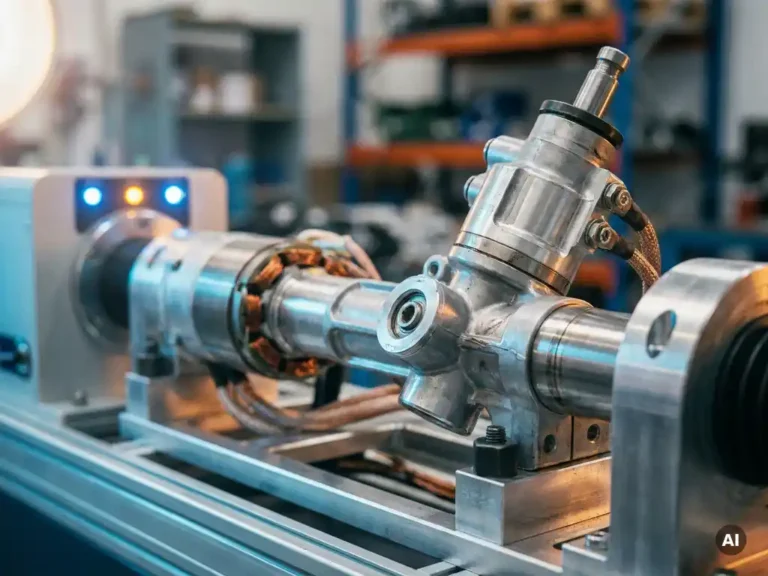
During rapid direction changes, an electric steering system experiences sharp current spikes, mechanical stress on the motor shaft, and sudden voltage transients across the controller. The motor must decelerate, stop, and accelerate in the opposite direction within milliseconds, which places simultaneous demands on the controller’s current regulation, thermal management, and motor feedback systems. The sections below break down each of those demands in detail.
What forces act on a power steering motor during direction reversal?
During a direction reversal, a power steering motor experiences a combination of inertial braking force, counter-electromotive force (back-EMF), and the mechanical load from the steering linkage itself. These forces act simultaneously and in opposition to the new commanded direction, requiring the motor to absorb and redirect energy rather than simply accelerate.
The most significant of these is inertial load. Even at low rotational speeds, the combined mass of the motor rotor, gearbox, and steering column resists the change in direction. The controller must apply reverse torque to overcome this inertia, which translates directly into a sharp current demand. At the same time, back-EMF from the spinning motor acts against the new drive voltage, creating a brief period where the effective voltage across the motor windings is the sum of the supply voltage and the back-EMF rather than the difference.
The mechanical side of the system adds further complexity. Steering linkages in forklifts, AGVs, and similar vehicles are often under lateral load during a direction change, meaning the motor is fighting both inertia and external mechanical resistance at the same moment. This combination is what makes rapid steering reversals one of the most electrically and mechanically demanding events in a vehicle’s operating cycle.
How does a motor controller manage current surges during steering reversals?
A motor controller manages current surges during steering reversals primarily through active current limiting, which caps the instantaneous current delivered to the motor windings regardless of the demanded torque. The controller monitors phase current in real time and modulates the switching duty cycle of its power devices to keep current within safe bounds while still delivering the fastest achievable reversal response.
In practice, this means the controller does not simply apply full reverse voltage the moment a direction change is commanded. Instead, it ramps the current according to a defined profile, balancing response speed against the thermal and electrical limits of both the motor and the switching devices. Controllers using field-oriented control (FOC) have a particular advantage here because they regulate torque-producing current (the d- and q-axis components) independently, allowing precise control even during the transient phase of a reversal.
Regenerative capability also plays a role. As the motor decelerates before reversing, some controllers recover the kinetic energy back into the battery bus rather than dissipating it as heat across braking resistors. This reduces the thermal load on the controller during the deceleration phase, leaving more thermal headroom for the subsequent acceleration in the new direction.
What causes overheating in electric steering controllers during aggressive maneuvers?
Overheating in electric steering controllers during aggressive maneuvers is caused by the repeated dissipation of power in the switching devices (typically MOSFETs or IGBTs) during high-current transients. Each direction reversal forces the power devices to switch rapidly while carrying elevated current, and the energy lost in each switching event accumulates as heat in the semiconductor junctions.
The problem compounds in duty-cycle terms. A single reversal generates a brief thermal spike. In applications like warehouse forklifts or AGVs navigating tight spaces, these reversals can occur dozens of times per minute. The junction temperature of the power devices may not fully recover between events, causing the average temperature to rise progressively until thermal protection activates or, in poorly designed systems, a device fails.
Thermal management at the component level is therefore as important as the controller’s electrical design. Mounting power devices on a substrate with poor thermal conductivity creates a bottleneck between the heat source and the heatsink, regardless of how large that heatsink is. This is why the thermal path from the MOSFET junction to the cooling surface is a primary engineering consideration in controllers intended for high-cycle steering applications.
How does sensorless motor control affect steering performance during fast reversals?
Sensorless motor control can degrade steering performance during fast reversals because it relies on back-EMF estimation to determine rotor position, and back-EMF drops to near zero at very low speeds and at standstill. The transition through zero speed during a direction reversal is precisely the point where sensorless algorithms are least reliable, which can cause a brief loss of torque control or an incorrect commutation event.
For traction applications, this limitation is manageable because the vehicle rarely needs to reverse instantaneously at full torque from a complete stop. Steering systems, by contrast, frequently operate at low speeds with high torque demands, including the zero-crossing moment of a reversal. A momentary loss of position accuracy at that point translates into a hesitation or jerk in the steering response, which is perceptible to the operator and can affect vehicle handling in precision tasks.
Sensor-based control, using a resolver, encoder, or Hall-effect sensors, maintains accurate rotor position data through the entire reversal cycle, including the zero-speed transition. For steering motors where directional authority at low speed is a safety and usability requirement, sensor-based feedback remains the more dependable approach.
What voltage and power ratings matter most for electric steering controllers?
For electric steering controllers, the most relevant ratings are peak current capability, continuous power dissipation, and bus voltage range. Peak current determines how quickly the controller can apply reverse torque during a direction change. Continuous power dissipation determines how many consecutive reversals the controller can handle before thermal limiting reduces performance.
Bus voltage range matters because steering systems in industrial vehicles operate across a wide range of battery chemistries and pack configurations, commonly from 24 V in smaller platforms up to 80 V or 96 V in larger industrial machines. A controller that covers this range without hardware changes simplifies integration across vehicle families and reduces the number of variants an OEM needs to qualify and stock.
Peak power ratings deserve particular attention. A controller rated at a given nominal power may be capable of two or three times that figure for short durations, which is exactly the profile of a steering reversal. Specifying a controller based on nominal power alone, without checking peak ratings and the thermal conditions under which those peaks are sustainable, is a common source of underspecification in steering system design. You can review the full motor controller range to compare how nominal and peak figures relate across different configurations.
Which industrial vehicles are most affected by steering reversal dynamics?
Counterbalance forklifts, reach trucks, and AGVs operating in confined warehouse environments are the industrial vehicles most affected by steering reversal dynamics. These platforms combine high vehicle mass, tight turning requirements, and high operational duty cycles, meaning the steering system is asked to reverse direction frequently and at significant load.
Scissor lifts and boom lifts present a different but related challenge. Their steering inputs tend to be slower, but the vehicles operate on uneven ground with unpredictable lateral forces on the steering linkage, which can amplify the effective load on the steering motor during corrections. Marine steering systems, particularly on electric vessels with joystick control, face rapid azimuth changes that create similar reversal dynamics to those of warehouse vehicles.
Golf cars and light personnel carriers are at the lower end of the severity scale, but even these platforms can generate meaningful reversal transients on tight courses or in loading dock environments. The common factor across all these applications is that the steering controller must handle transient loads that are disproportionately large relative to the vehicle’s steady-state power consumption, which is why steering controller selection warrants the same level of engineering scrutiny as traction controller selection.
How the SuperSigma2 addresses electric steering system demands
The SuperSigma2 from DMC is built around the specific electrical and thermal demands that rapid direction changes place on a power steering controller. Its architecture addresses the core challenges described throughout this article:
- A bus voltage range of 24 V to 108 V covers the full span of industrial vehicle battery configurations, from compact AGVs to heavy forklifts, without requiring hardware changes between platforms.
- Nominal power up to 30 kW with peak capability up to 60 kW provides the current headroom needed to apply full reverse torque during direction changes without triggering thermal limiting under normal duty cycles.
- Fully automated motor and sensor tuning removes the manual calibration burden from commissioning, ensuring the controller operates with accurate motor parameters from first power-on, which directly affects how cleanly it handles low-speed transients like direction reversals.
- Compatibility with AC induction, PMS, and IPM motor types on a single platform gives OEM engineers flexibility to select the motor best suited to their steering application without changing controller hardware.
- DMC’s proprietary IMS (Insulated Metal Substrate) technology mounts MOSFET power devices directly onto a metal PCB, keeping junction temperatures lower during the high-frequency switching events that occur during aggressive steering maneuvers.
- Dual-processor architecture with full CANopen support, available since early 2023, enables tight integration with vehicle control systems for coordinated steering and traction management.
If you are specifying a controller for a steering application with demanding reversal requirements, contact the DMC team to discuss your motor type, duty cycle, and voltage requirements directly with their engineers.
Related Articles
- How do traction, steering and hydraulic loads compete for power in a battery-powered machine?
- Field weakening in PMSM vs IPM motors: what actually changes?
- FOC vs traditional PWM control: what's the performance difference?
- What are the main types of motor controllers, and how do they differ?
- How much more efficient is IMS cooling than a traditional heatsink?