
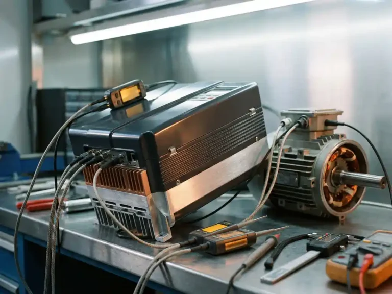
Motor tuning sits at the heart of how well an electric vehicle actually performs in practice. It is the process of configuring a motor controller to match the specific electrical and mechanical characteristics of the motor it drives, and when done well, the difference in responsiveness, efficiency, and reliability is substantial. Whether the application is a forklift navigating a warehouse or an AGV following a precision path, the quality of the tuning directly shapes what the motor can deliver.
The term covers a range of adjustments, from basic parameter entry to fully automated calibration routines, and the approach taken has real consequences for everything from energy consumption to thermal load. Understanding what motor tuning involves, and why it matters, helps operators and engineers make better decisions about their motor controller setup from the outset.
How motor tuning affects real-world vehicle performance
Motor tuning determines how accurately the controller interprets and responds to motor behavior under load. A motor that is poorly tuned relative to its controller will exhibit sluggish acceleration, inconsistent torque delivery, or instability at higher speeds, none of which are acceptable in demanding industrial or vehicle applications.
When the controller parameters are correctly matched to the motor, the system can apply current precisely, respond to load changes smoothly, and maintain stable operation across the full speed range. This translates into better handling, more predictable braking, and reduced energy waste. In battery-driven vehicles where range and battery life matter, even modest improvements in motor control efficiency compound over the course of a working day.
Key parameters adjusted during motor tuning
Motor tuning is not a single adjustment but a structured process involving several interdependent parameters. The specific values required depend on the motor type, its rated voltage and current, and the nature of the application.
For AC induction motors, key parameters include slip frequency, magnetizing current, and rotor time constant. For PMAC motors (both surface-mounted and interior permanent magnet types), the focus shifts to d-axis and q-axis inductance values, back-EMF constant, and flux linkage. Getting these values right is what allows the controller to execute field-oriented control accurately, which in turn governs how torque is produced and regulated across the operating range.
Beyond motor-specific electrical parameters, tuning also involves setting acceleration and deceleration ramp rates, current limits for peak and continuous operation, and speed regulation behavior. These settings interact with each other, so adjusting one without accounting for the others can introduce performance problems that are difficult to diagnose after the fact.
Manual vs. automated motor tuning approaches
Traditionally, motor tuning required engineers to measure motor parameters using external test equipment, then manually enter the values into the controller. This approach demands a solid understanding of motor theory and takes considerable time, particularly when tuning multiple units or working with motors for which documentation is incomplete.
Automated motor tuning changes this significantly. Modern motor speed controllers can execute an automated identification routine that applies controlled test signals to the motor and measures its electrical response directly. The controller then calculates the required parameters and configures itself accordingly, without the need for manual measurement or specialist intervention.
The practical benefit is consistency. Automated routines remove the variability that comes from manual data entry and reduce the risk of configuration errors. They also make it far more straightforward to commission replacement motors or to tune a fleet of vehicles where individual motor characteristics may differ slightly from unit to unit.
Sensorless motor control and its tuning implications
Conventional motor control relies on physical sensors, typically encoders or resolvers, to track rotor position and speed. Sensorless control eliminates this hardware dependency by estimating rotor position mathematically from measured motor voltages and currents.
This approach simplifies installation and reduces potential failure points, but it places greater demands on the tuning process. The accuracy of position estimation depends entirely on how well the controller’s internal motor model reflects the actual motor. If the tuned parameters deviate significantly from the real values, the sensorless estimator can lose track of rotor position, particularly at low speeds or under sudden load changes.
Sensorless operation therefore requires careful initial tuning, and automated tuning routines are especially valuable here because they establish an accurate motor model before the sensorless algorithm is engaged. Once correctly configured, sensorless control can match sensor-based performance in many applications, with the added benefit of reduced wiring complexity and fewer components that can wear or fail.
Thermal management and its role in sustained tuning accuracy
Tuning a motor controller is not a one-time event that holds indefinitely under all conditions. Motor parameters, particularly winding resistance, shift with temperature. As a motor heats up during operation, its electrical characteristics change, and a controller that was tuned at ambient temperature may behave differently once the system has been running under load for an extended period.
This is where thermal management becomes directly relevant to tuning quality. Controllers that keep their power switching devices at lower operating temperatures maintain more stable internal references and can apply corrections more accurately. When the controller itself runs cooler, it is better positioned to compensate for motor parameter drift rather than compounding it.
The design of the controller’s thermal architecture therefore has a direct bearing on how reliably the tuned parameters hold across a full working cycle. Controllers built with superior heat dissipation capability sustain tuning accuracy more effectively than those that run hot under continuous load, which matters considerably in applications like forklifts or boom lifts where duty cycles are demanding and consistent performance is expected throughout a shift.
How DMC helps with motor tuning
DMC’s SuperSigma2 and Sigma2N controller range were developed with motor tuning as a core capability rather than an afterthought. The controllers support both AC induction and PMAC motors across a wide voltage range, and every unit in the range includes a fully automated motor and sensor tuning routine that identifies motor parameters directly without requiring external measurement equipment or specialist configuration by hand.
- Automated tuning runs a controlled identification sequence at commissioning, establishing an accurate motor model that feeds directly into the field-oriented control algorithm.
- Sensorless motor control is available across the range, with the automated tuning process providing the accurate parameter base that sensorless operation depends on.
- DMC’s proprietary IMS (Insulated Metal Substrate) technology mounts power devices directly onto a metal PCB, keeping switching components cooler and supporting consistent control accuracy under sustained load.
- The range covers nominal battery voltages from 24V to 108V and nominal powers up to 30kW, with peak powers up to 60kW, making it applicable across AGVs, forklifts, scissor lifts, marine platforms, and more.
If you are working through a motor controller selection or have questions about tuning compatibility with a specific motor, contact the DMC team directly to discuss your application requirements.