
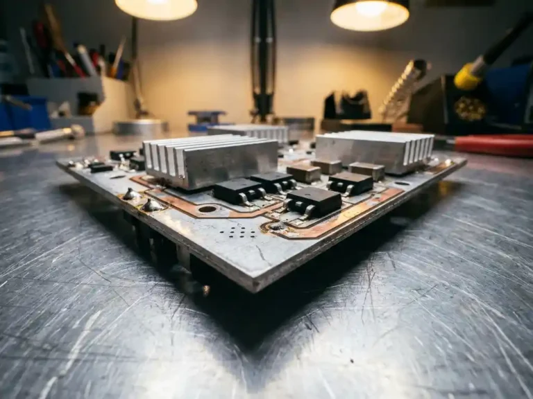
When a motor controller fails in the field, heat is almost always part of the story. Power switching devices generate significant thermal load during operation, and how well a controller manages that heat determines its reliability, lifespan, and performance under demanding duty cycles. One of the less-discussed but genuinely important factors in controller design is the substrate technology used to mount those power devices. IMS substrate, short for Insulated Metal Substrate, represents a specific approach to this problem that differs meaningfully from conventional printed circuit board construction.
Understanding what IMS substrate is and why it matters gives field engineers a clearer picture of why certain motor controllers behave differently under load, and what to expect during installation, commissioning, and long-term maintenance.
How IMS substrate works inside a motor controller
A conventional PCB uses a fiberglass-based laminate (typically FR4) as its base material. This works well for signal-level electronics, but fiberglass is a poor thermal conductor. When power switching devices such as MOSFETs are mounted on a standard PCB, the heat they generate has to travel through that insulating material before it can reach any external heatsink. That thermal resistance adds up quickly at high switching frequencies and high current loads.
IMS substrate replaces the fiberglass base with a metal core, typically aluminum. A thin dielectric layer sits between the metal base and the copper circuit layer, providing the necessary electrical isolation while allowing heat to pass through far more efficiently than fiberglass ever could. The result is that heat generated at the MOSFET junction transfers directly into the metal substrate and dissipates across the board’s surface area, rather than building up at the component itself. This is what makes IMS effective: the substrate itself acts as an integral heatsink, built directly into the board structure.
Thermal advantages over conventional PCB designs
The practical difference between IMS and standard PCB construction becomes clear when you look at junction temperatures under load. On a conventional board, a MOSFET running at high current will develop a significant temperature gradient between its junction and the board surface. That gradient represents trapped heat, and trapped heat accelerates component degradation over time.
IMS substrate reduces that gradient by giving heat a low-resistance path out of the component and into the metal base. Lower operating temperatures at the junction translate directly into longer device life and more consistent switching performance. Controllers built on IMS can also handle higher peak currents for shorter durations without the thermal runaway risk that would affect a standard PCB design under the same conditions.
There is also a structural benefit. The metal core adds rigidity to the board, which matters in mobile and industrial applications where vibration is a constant factor. A stiffer board is less prone to solder joint fatigue, which is another common failure mode in controllers that see regular mechanical stress.
IMS substrate in the SuperSigma2 controller range
DMC developed its proprietary IMS technology as a core element of the SuperSigma2 range, applying it to support cost-effective SMD MOSFET power devices mounted directly onto the metal PCB. Rather than relying on bulky external heatsink assemblies or thermally conductive pads with variable contact quality, the SuperSigma2 integrates heat management into the board itself.
The SuperSigma2 operates on nominal battery voltages from 24V up to 108V, with nominal power up to 30 kW and peak power reaching 60 kW. At those power levels, thermal management is not a secondary concern. The IMS approach keeps switching devices cooler across the operating range, which supports the controller’s ability to handle AC induction, PMS, and IPM motor types within a single platform without derating performance to protect components.
The combination of IMS heat dissipation with fully automated motor and sensor tuning means the SuperSigma2 can be commissioned accurately across a wide range of motor configurations while the thermal design handles the sustained load that follows. Sensorless control is also available, though DMC deliberately does not apply it for traction applications where precise torque control is required.
What IMS substrate means for field installation and maintenance
From a practical standpoint, IMS substrate changes a few things about how a controller behaves in the field. Because the board itself manages heat distribution, the controller is less sensitive to variations in external heatsink mounting quality. On a conventional design, an imperfect thermal interface between the controller and its heatsink can have a significant effect on operating temperatures. With IMS, the internal heat path is already doing meaningful work before any external surface is involved.
During maintenance inspections, controllers built on IMS substrate tend to show fewer signs of heat-related stress on the board itself. Discoloration around power devices, lifted pads, or cracked solder joints are all indicators of thermal cycling damage that IMS construction reduces. This makes fault diagnosis more straightforward: if those signs are present on an IMS-based board, the cause is likely an external thermal issue rather than a design limitation.
Replacement and repair considerations are also worth keeping in mind. SMD MOSFETs on an IMS board require appropriate rework equipment and technique, since the metal substrate conducts heat away from the soldering area more aggressively than fiberglass. This is not a complication unique to IMS, but it is something to account for when planning component-level repairs in the field.
How DMC’s SuperSigma2 addresses thermal management in demanding applications
DMC’s SuperSigma2 range was built around IMS technology as a deliberate design choice, not an afterthought. For field engineers working with battery-driven electric vehicles and industrial platforms, that choice has concrete implications:
- Sustained high-current operation with reduced thermal derating risk across the 24V to 108V voltage range
- A single controller platform supporting AC induction, PMS, and IPM motors with automated tuning, reducing the number of controller variants to stock and service
- Integral heat management that is less dependent on external mounting conditions, simplifying installation in tight or variable enclosures
- Dual processor architecture with full CANopen support, available since early 2023, for integration into modern vehicle and industrial control networks
- Sensorless control capability where applicable, with the option to apply sensor-based control for traction applications requiring precise torque response
For engineers evaluating controller options or troubleshooting existing installations, the thermal architecture of the controller is worth understanding before a problem develops rather than after. To learn more about the SuperSigma2 range or discuss a specific application, visit the DMC products page or get in touch with the team directly.