
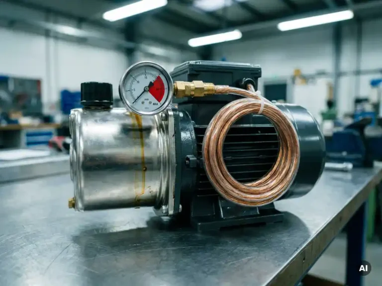
When a hydraulic function in an electric vehicle or industrial machine reaches its pressure limit, the pump motor stalls or comes close to stalling. At that point, it draws maximum current while producing little or no useful flow, creating a condition that the motor controller must manage carefully to prevent damage. The sections below work through each aspect of that behavior, from current spikes to controller configuration.
What happens to motor current when hydraulic pressure peaks?
When hydraulic pressure reaches its maximum, the pump load increases sharply and motor speed drops. As speed falls, the back-EMF produced by the motor decreases, which allows more current to flow from the controller. In a stall condition, current can reach several times the rated running value within milliseconds.
This current spike is not a fault in itself. It is the motor’s natural response to a mechanical load it cannot overcome. The problem is duration. A brief pressure peak at the end of a lift cycle is normal. Sustained operation at peak pressure, where the pump is essentially deadheaded against a closed circuit, keeps the motor in a high-current, low-speed state that generates substantial heat in both the windings and the switching devices inside the controller.
For engineers designing pump motor systems, the key design question is not whether this current spike will occur, but how long it will be allowed to persist and what mechanism will terminate it.
What is the role of the pressure relief valve in an electric pump system?
The pressure relief valve is the hydraulic system’s primary protection against overpressure. When system pressure reaches the valve’s set point, it opens a bypass path that diverts flow back to the tank, preventing pressure from rising further. In doing so, it also maintains a defined load on the pump motor rather than allowing pressure to climb indefinitely.
In an electric pump system, the relief valve and the motor controller work together, though they operate on different physical principles. The valve responds to pressure directly. The controller responds to electrical signals, primarily current and speed. When the relief valve opens, the pump continues to run and flow circulates through the bypass. The motor is still driving the pump under load, so current remains elevated. The relief valve removes the pressure hazard but does not remove the thermal hazard from the motor.
This distinction matters for system design. A hydraulic system that relies entirely on the relief valve for pump protection will still expose the motor to sustained overload conditions every time that valve opens for more than a few seconds.
How does the motor controller respond to a stalled or overloaded pump?
A motor controller responds to pump stall or overload primarily through current limiting and thermal protection. When detected current exceeds the programmed limit, the controller reduces its output voltage to bring current back within bounds. If the overload persists, a thermal model inside the controller accumulates a calculated temperature value and eventually triggers a controlled shutdown or a reduction in available power.
The speed at which the controller responds depends on how aggressively the current limit is set and how the thermal model is configured. A tightly set current limit protects the motor quickly but may interrupt legitimate working cycles. A loose limit gives more headroom for short peaks but allows more energy to enter the motor before protection activates.
Some controllers also monitor motor speed directly. If speed drops below a defined threshold while current is high, the controller can interpret this as a stall condition and respond faster than a pure thermal model would. This is particularly useful in pump applications where stall can happen suddenly rather than gradually.
Why does an electric pump motor overheat at sustained pressure limits?
An electric pump motor overheats at sustained pressure limits because it is doing electrical work without producing proportional mechanical output. At or near stall, nearly all of the electrical energy drawn from the battery converts to heat in the motor windings rather than to hydraulic flow. The motor’s cooling capacity, which depends partly on airflow generated by rotation, is also at its lowest when speed is low.
AC induction motors and permanent magnet motors behave slightly differently here. An induction motor draws high current at low slip frequencies to maintain torque, which generates significant rotor heating. A permanent magnet motor can produce high torque at stall with less rotor loss, but stator winding temperatures still rise quickly under sustained high current.
The thermal time constant of the motor winding is typically measured in minutes, not seconds. This means a motor can tolerate brief stall events without reaching damaging temperatures, but repeated or extended pressure-limit conditions accumulate heat faster than the motor can dissipate it. Proper controller configuration is the practical tool for managing this accumulation before it causes insulation degradation or demagnetization in permanent magnet types.
What’s the difference between pressure cutoff and pressure limiting in hydraulic pump control?
Pressure cutoff and pressure limiting are two distinct strategies for managing pump behavior at high pressure. Pressure cutoff stops the pump entirely when a set pressure is reached. Pressure limiting reduces pump output, typically by reducing motor speed or torque, to maintain pressure at a target value without stopping flow completely.
Pressure cutoff is simpler to implement. A pressure switch or a signal from the machine’s control unit tells the motor controller to stop driving the pump. This eliminates the overload condition immediately and is well suited to applications where holding pressure is not required and the hydraulic circuit has sufficient line volume to maintain position.
Pressure limiting, sometimes implemented through a proportional pressure control valve combined with variable motor speed, keeps the pump running at reduced output to compensate for any leakage in the circuit. This approach is more energy-efficient in applications where position must be held over time, such as a loaded forklift mast. It requires a controller that can accept a pressure feedback signal and regulate motor speed accordingly, which places greater demands on the control architecture.
How should a pump motor controller be configured for hydraulic pressure management?
A pump motor controller should be configured with a current limit matched to the motor’s rated continuous current, a stall detection threshold based on the expected minimum operating speed, and a thermal model that reflects the motor’s actual thermal time constant. These three parameters work together to protect the motor across the range of conditions the pump will encounter in service.
Beyond those core settings, the controller’s response to a pressure cutoff signal deserves attention. When a cutoff signal arrives, the controller should ramp down motor torque smoothly rather than cutting output instantly. An abrupt stop can cause a pressure surge in the hydraulic line, particularly if the pump has been running at high flow. A controlled deceleration ramp of even a few hundred milliseconds reduces that surge significantly.
For applications where the pump motor must restart frequently against a pressurized system, the controller’s starting behavior matters as much as its stopping behavior. The controller must be able to produce adequate torque at low speed to overcome system pressure at startup without triggering its own overcurrent protection during the first few cycles of a working sequence.
How the SuperSigma2 supports hydraulic pump control
The SuperSigma2 controller range from DMC addresses the specific demands of electric pump applications through a combination of configurable protection parameters and flexible motor compatibility. Key capabilities relevant to hydraulic pressure management include:
- Adjustable current limits and thermal models that can be tuned to match the motor’s rated characteristics and the duty cycle of the hydraulic application
- Stall detection and controlled response, allowing the controller to act on a low-speed, high-current condition before the motor’s thermal limits are reached
- Fully automatic motor and sensor tuning, which removes the risk of misconfigured parameters that could leave a pump motor underprotected or unnecessarily restricted
- Support for AC induction, PMS, and IPM motor types within a single platform, giving OEM engineers the flexibility to select the motor technology best suited to the hydraulic system’s pressure and flow requirements
- CANopen communication, enabling the vehicle control unit to send pressure cutoff or speed reference signals directly to the controller for closed-loop hydraulic pressure management
- IMS-based thermal management, which keeps switching device temperatures lower and extends controller reliability in the sustained high-current conditions that hydraulic pressure limits produce
If you are configuring a pump controller for a specific hydraulic application or need to discuss motor compatibility and protection settings, contact the DMC team directly for application support.
Related Articles
- Why does pump duty cycle matter in battery-powered hydraulic machinery?
- How does operating on a slope affect an electric aerial work platform?
- What makes the SuperSigma2 different from earlier DMC controller ranges?
- FOC vs traditional PWM control: what's the performance difference?
- Is vector control necessary for electric vehicle drivetrains?