
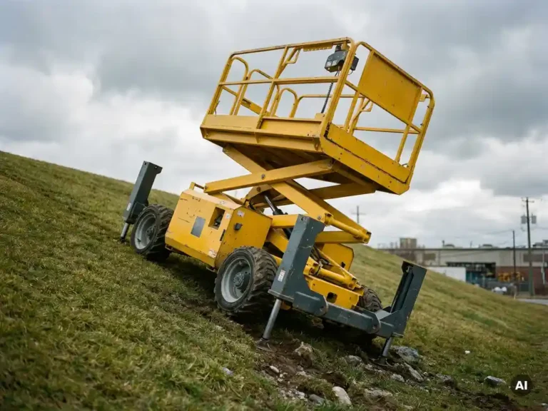
Operating on a slope places an electric aerial work platform under compounding mechanical and electrical stress. The platform’s stability margin narrows, the drive motors work harder, battery discharge accelerates, and onboard safety systems become the primary line of defence against tip-over. These effects interact with each other, so understanding them individually gives engineers and specifiers a clearer picture of what slope operation actually demands from an AWP system.
What happens to an aerial work platform’s stability on a slope?
When an electric aerial work platform operates on a slope, the machine’s centre of gravity shifts toward the downhill side, reducing the effective stability envelope. The steeper the incline, the smaller the margin between the platform’s current load distribution and the tipping threshold. With the work platform elevated, this effect is amplified because the raised mass acts as a lever arm against the base.
Stability is governed by the relationship between the machine’s centre of gravity and its tipping axis, which runs along the downhill wheels or outriggers. As the slope angle increases, the horizontal distance between the centre of gravity and the tipping axis shrinks. At the same time, any lateral movement of the operator, a load shift, or an abrupt drive input can push the centre of gravity past that axis. This is why AWP manufacturers specify separate stability ratings for working height and travel height: a machine that is stable while driving on flat ground may reach its tipping limit at a much lower platform height when traversing an incline.
Wind loading adds another variable on slopes. At elevation, lateral wind force combines with the gravity-induced lean to place asymmetric stress on the structure, which is why many AWP standards require reduced rated capacity or restricted platform height when operating above certain slope angles.
How does slope angle affect the electric drivetrain and motor load?
Slope angle directly increases the tractive force the drive motors must produce. On a gradient, the motors must overcome both rolling resistance and the gravitational component acting along the slope. As the incline steepens, the torque demand rises, which means higher current draw, more heat generated in the motor windings and the motor controller, and a faster rate of battery discharge.
The relationship is not linear in practice. At low speeds on a moderate slope, a well-matched motor controller can manage the load smoothly. But on steeper inclines, particularly during acceleration from rest or when holding position on a grade, peak current demands can spike significantly above the continuous rating. This is where thermal management in the controller becomes a limiting factor: sustained high-current operation at elevated temperatures degrades switching device performance and, over time, reliability.
Regenerative braking behaviour also changes on slopes. When descending, the motor transitions to generator mode, feeding energy back to the battery. The controller must manage this transition carefully to avoid overvoltage on the battery bus, which is a real concern on longer or steeper descents where regenerative current can exceed what the battery’s charge acceptance allows at that state of charge.
What safety systems limit AWP operation on inclines?
Electric aerial work platforms use a combination of tilt sensors, height-speed interlocks, and drive cutout logic to limit operation on inclines. The tilt sensor, typically a multi-axis inclinometer, monitors the platform’s angle relative to level ground and triggers graduated responses as the machine approaches its rated slope limit.
At a defined threshold, the control system may restrict platform height, reduce drive speed, or prevent the platform from being raised at all. If the tilt angle exceeds the safe operating limit while the platform is elevated, the system will typically alarm and lock out further drive or lift commands until the machine returns to acceptable ground conditions. Some machines implement a soft cutout rather than a hard stop, progressively reducing drive torque as the angle approaches the limit to give the operator a controlled response rather than a sudden loss of drive.
Outrigger-equipped machines add another layer of protection. The control logic may require all outriggers to be deployed and load sensing confirmed before allowing the platform to be raised on any terrain with a detected incline. Load management systems on larger boom lifts monitor platform load in real time and can reduce the permitted working envelope when the machine is on a slope, compensating for the reduced stability margin.
Why does battery performance change when operating on a slope?
Battery performance on a slope changes because the drive system draws higher current than it would on flat ground, which accelerates discharge and increases internal heating within the battery pack. Higher current draw also increases resistive losses inside the cells, which reduces the effective energy available from a given state of charge.
The practical consequence is that runtime estimates based on flat-ground operation will overstate actual range on a slope. For lithium-based packs, the battery management system may apply current limits at higher temperatures or at low state of charge, which can reduce available drive torque precisely when the machine is working hardest. Lead-acid packs are more sensitive to high-rate discharge, and their voltage sag under heavy load can cause the controller’s undervoltage protection to trigger earlier than expected.
Regenerative braking on descents partially offsets the extra energy consumed on ascents, but the recovery is rarely a one-to-one exchange. The efficiency of the regeneration cycle depends on the controller’s braking current limits, the battery’s charge acceptance rate, and the duration of the descent. In applications where an AWP regularly operates on sloped terrain, this energy budget should be factored into battery sizing and charging cycle planning.
What are the maximum slope ratings for electric aerial work platforms?
Maximum slope ratings for electric aerial work platforms vary by machine type, but most scissor lifts are rated for travel on gradients up to 25% (approximately 14 degrees) on flat ground with the platform lowered, and significantly less when the platform is raised. Boom lifts typically carry more conservative slope ratings due to their higher centre of gravity and extended reach geometry.
These ratings are specified by the manufacturer and defined under standards such as EN 280 in Europe and ANSI/SAIA A92 in North America. The rated slope for travel and the rated slope for working are usually different values, and both are measured with the machine on a firm, level surface relative to the slope. Operators and site planners should treat these figures as absolute limits, not guidelines, because the consequences of exceeding them are structural and not recoverable through operator skill.
It is also worth distinguishing between the slope the machine can travel on and the slope it can work on. Many machines permit travel on a moderate gradient only when the platform is fully lowered, and restrict working height to a fraction of maximum when any incline is detected. Site surveys for AWP deployment should map the gradient across the entire travel path, not just the working position.
How should motor controllers be configured for slope-heavy AWP applications?
Motor controllers for AWP applications on sloped terrain should be configured to manage sustained high-torque demand, controlled regenerative braking, and smooth anti-rollback behaviour. The key parameters are torque limits, current ramp rates, regenerative braking current, and the response of the speed control loop under varying load conditions.
Anti-rollback is particularly important. When an AWP stops on a slope, the controller must hold the machine stationary without relying on the mechanical brake alone. This requires the controller to maintain a holding torque actively, then release it in a coordinated sequence with the brake when the operator commands movement. Poorly tuned anti-rollback results in a brief roll before the motor takes up the load, which is both a safety concern and a source of mechanical stress on the drivetrain.
Regenerative braking current limits must be set with the battery’s charge acceptance rate in mind. Setting the limit too high risks overvoltage faults on long descents; setting it too low means more energy is dissipated as heat in the mechanical brake rather than recovered. The correct value depends on the battery chemistry, pack size, and the typical descent profile for the application.
Thermal protection settings in the controller should reflect the duty cycle expected on slopes. Continuous operation at high torque generates more heat than intermittent flat-ground use, and the controller’s thermal model should be configured to reflect this. Autotuning capabilities that characterise the motor accurately at commissioning help the controller maintain precise torque control across the full operating range, which is especially valuable when load conditions vary as they do on uneven terrain. For more detail on the available motor controller options, the product range covers configurations suited to these demanding duty cycles.
How the SuperSigma2 addresses slope operation in AWP applications
The SuperSigma2 controller range from DMC is designed for exactly the kind of demanding, variable-load conditions that slope-heavy AWP applications impose. Several of its core capabilities are directly relevant to the challenges described above:
- Fully automated motor and sensor tuning characterises the motor accurately at commissioning, giving the controller a precise model of the drive system from the start. This translates to consistent torque control on inclines, where inaccurate motor parameters lead to instability in the speed and current control loops.
- The IMS (Insulated Metal Substrate) thermal architecture mounts power switching devices directly onto a metal PCB, dissipating heat more effectively than conventional designs. This matters on slopes because sustained high-current operation is the norm, not the exception.
- Support for AC induction, PMS, and IPM motor types within a single platform gives OEM engineers flexibility to select the motor technology best suited to the torque and efficiency profile of their AWP design, without changing the controller platform.
- Operating across 24V to 108V nominal battery voltage with peak power up to 60 kW, the SuperSigma2 covers the range from compact electric scissor lifts to larger boom lift platforms.
- CANopen integration (standard since early 2023) allows the controller to communicate directly with the AWP’s tilt sensor logic, safety interlocks, and platform management system, enabling coordinated slope response across the full machine control architecture.
For OEM engineers specifying a controller for an AWP that will regularly operate on inclines, the combination of accurate autotuning, robust thermal management, and open communication architecture makes the SuperSigma2 a technically grounded choice. To discuss specific application requirements, contact the DMC team directly.
Related Articles
- What happens to a scissor lift electrical system while the platform is being raised?
- What happens to an electric steering system during rapid direction changes?
- Brushless vs brushed motor controllers: what's the real difference?
- How do you choose the right motor for an industrial EV application?
- What is sensorless motor control?