
When setting up a motor controller for an electric vehicle or industrial platform, one of the earliest decisions is how to tune the motor. The process determines how well the controller understands the motor it is driving, and getting it wrong affects everything from efficiency and thermal performance to responsiveness and reliability. Both manual motor tuning and autotuning are legitimate approaches, but they work differently, suit different situations, and carry different risks. Understanding what separates them helps engineers and technicians make better decisions from the start.
The distinction matters more than it might initially appear. AC induction motors and PMAC motors each have their own parameter sets, and the margin for error during motor controller tuning is narrow. A miscalibrated parameter can cause instability, excessive heat, or poor torque response under load. The method used to establish those parameters shapes the outcome significantly.
How each tuning method works in practice
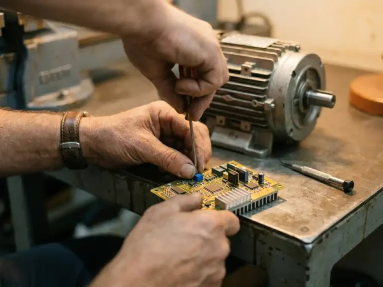
Manual motor tuning involves entering motor parameters directly into the controller configuration, typically by referencing the motor datasheet or by running a series of tests and recording measurements. The technician supplies values such as stator resistance, inductance, and flux-related parameters, then adjusts them based on observed motor behavior. This is a sequential, hands-on process that requires both the right instruments and a solid understanding of motor theory.
Autotuning, by contrast, runs a controlled test sequence automatically. The controller applies known signals to the motor, measures the electrical responses, and calculates the relevant parameters without manual input. The result is a parameter set derived from the actual motor connected to the actual controller, under real operating conditions rather than datasheet assumptions. This distinction is important because datasheet values are often nominal figures that do not fully reflect manufacturing variation or cable effects in a specific installation.
Where manual tuning still has a role
Despite the clear appeal of automation, manual tuning is not obsolete. There are situations where running an automated test sequence is impractical or where the engineer has precise knowledge of the motor that makes manual entry faster and more reliable. Replacement scenarios where a known motor type is being swapped into a tested configuration are one example. Another is when the mechanical load cannot be safely disconnected during the tuning sequence, making automated excitation of the motor a risk.
Manual tuning also gives experienced engineers a degree of interpretive control. If the motor datasheet is from a trusted source and the installation is straightforward, entering parameters manually can be quicker than running a full automated sequence. The limitation is that this approach depends heavily on the accuracy of the source data and the skill of the person entering it. Errors compound quietly and may not surface until the system is under load.
What autotuning handles automatically — and how
Automated motor tuning removes several of the most error-prone steps in the setup process. During a typical autotuning sequence, the controller applies low-level voltage signals to the motor windings and measures the resulting current responses. From these measurements, it calculates stator resistance and leakage inductance. For PMAC motors, the sequence also identifies flux linkage and, in some implementations, the rotor position offset relative to the encoder or resolver.
The value here is not just convenience. Autotuning captures the actual electrical characteristics of the motor as installed, accounting for wiring length, connector resistance, and any variation from nominal datasheet values. For AC induction motor tuning and PMAC motor tuning in particular, where the parameter sensitivity is high, this measured approach consistently produces a more accurate starting point than manual entry. Some controllers also support sensorless motor control, where the autotuning process must establish a reliable motor model without any position feedback device, making the accuracy of the automated characterization even more consequential.
Key differences in setup time and error risk
Setup time is one of the clearest practical differences between the two methods. Manual tuning, done carefully, can take considerable time, particularly if the engineer is working through iterative adjustments after initial entry. Autotuning typically completes its measurement sequence in a matter of minutes and delivers a usable parameter set immediately. For production environments or field service situations, that difference adds up.
Error risk is the other significant variable. Manual entry introduces the possibility of transcription errors, unit mismatches, or outdated datasheet values. These mistakes are not always obvious at startup and can cause problems that only appear under specific load conditions. Autotuning largely removes this category of error, though it introduces its own requirements: the motor must be in a state where it can be safely excited, and the measurement conditions should be representative of normal operation. A poorly executed autotuning sequence on a mechanically loaded motor can still produce inaccurate results.
Choosing the right approach for your application
The appropriate tuning method depends on the specific application, the available motor data, and the constraints of the installation environment. For new installations using unfamiliar motors, autotuning is generally the more reliable path. It removes dependence on datasheet accuracy and gives the controller a measured characterization of the specific unit installed. This is especially relevant in applications like AGVs, forklifts, and electric vehicle platforms where consistent performance across multiple units matters.
Manual tuning remains a reasonable choice when the motor is well-characterized, the installation is a known quantity, and the technician has the experience to enter and verify parameters confidently. It can also be the only option when the mechanical configuration prevents safe motor excitation during setup. In practice, many experienced engineers use autotuning as the default and reserve manual adjustment for fine-tuning specific behaviors after the initial characterization is complete. The two approaches are not mutually exclusive, and understanding both provides more flexibility when conditions are not ideal.
How DMC’s SuperSigma2 simplifies motor controller tuning
DMC’s SuperSigma2 motor controllers are designed to make both tuning approaches practical without requiring specialist tools or extended commissioning time. Key capabilities include:
- Fully automated motor and sensor tuning built into every SuperSigma2 unit, covering AC induction and PMAC (PMS and IPM) motors across the full voltage range from 24V to 108V
- Sensorless motor control support, with autotuning establishing the motor model without requiring a physical position sensor
- Compatibility with a wide range of applications, from single traction drives in forklifts and stackers to dual traction and power-steering configurations in AGVs and hybrid platforms
- Custom configuration options for applications where standard tuning sequences need adjustment to fit specific mechanical or electrical constraints
The result is a controller range that reduces commissioning time and minimizes the risk of parameter errors, whether the installation calls for automated tuning or manual setup. To discuss which configuration suits your application, contact the DMC team directly.
Related Articles
- How does operating on a slope affect an electric aerial work platform?
- Why do aerial work platforms have very different drive and lift duty cycles?
- What's different about a series-wound motor controller compared to AC or PMS?
- Motor selection mistakes that cause controller compatibility problems
- When should you not use sensorless control?