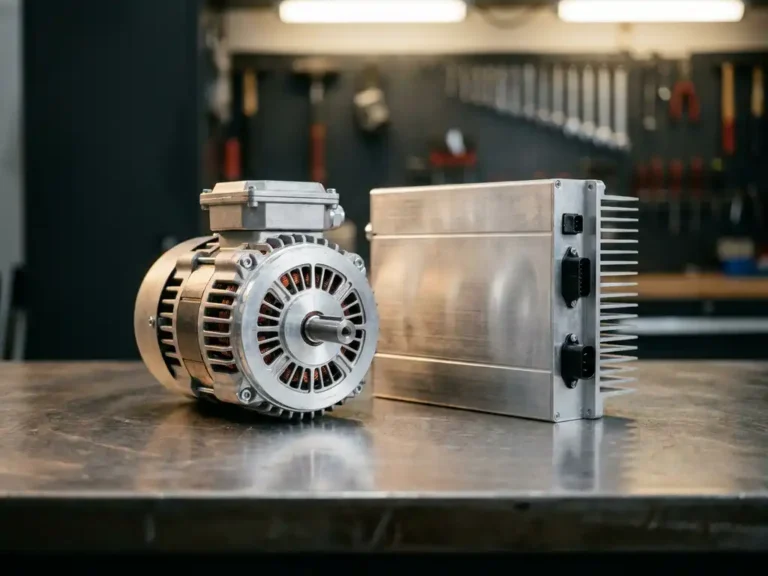
A motor and an inverter are two distinct components that work together in an electric drivetrain. The motor is the mechanical output device – it converts electrical energy into rotational force. The inverter is the power electronics stage that converts DC battery power into the AC waveform the motor needs to run. Without the inverter, most modern motors cannot function at variable speeds.
Understanding where one ends and the other begins matters in practice for anyone specifying, commissioning, or troubleshooting electric vehicle systems. The sections below work through the most common questions engineers ask when drawing that line.
What does an inverter actually do in an electric drivetrain?
An inverter takes direct current from a battery pack and converts it into alternating current at a controlled frequency and voltage. In an electric drivetrain, this conversion is what allows the motor to run at variable speeds rather than at a fixed rate determined by the supply frequency. The inverter switches its power transistors at high frequency to synthesize a smooth AC waveform from a DC source.
The switching is done using power devices such as MOSFETs or IGBTs, arranged in a three-phase bridge for AC motors. By adjusting the frequency of the output waveform, the inverter directly controls motor speed. By adjusting the amplitude, it controls torque. This is why the inverter is often described as the brain of the drivetrain – it translates a speed or torque demand signal into the precise electrical conditions the motor requires at any given moment.
In battery-powered vehicles, the inverter also manages regenerative braking by reversing the energy flow, allowing the motor to act as a generator and return energy to the battery during deceleration.
How does an electric motor convert electrical energy into motion?
An electric motor converts electrical energy into mechanical rotation through electromagnetic interaction. When current flows through the motor’s windings, it creates a magnetic field. The interaction between this field and the rotor – either through induction or through permanent magnets – produces a rotational force called torque.
In an AC induction motor, the stator windings produce a rotating magnetic field. The rotor, which is not directly connected to the supply, has currents induced into it by that rotating field. The difference in speed between the rotating field and the rotor (called slip) is what sustains the torque. In a permanent magnet AC motor (PMAC), the rotor carries embedded magnets that lock onto the rotating stator field, producing torque with higher efficiency and better power density at lower speeds.
The practical consequence for system designers is that the motor’s torque and speed characteristics are tightly linked to how the inverter drives it. The motor does not set its own operating point – the inverter does.
Can a motor run without an inverter?
A DC brush motor can run directly from a battery without an inverter, because it uses mechanical commutation to manage the internal switching. AC motors – including induction and PMAC types – cannot run at variable speed from a battery without an inverter, because they require a controlled AC waveform that a battery cannot supply on its own.
Connecting an AC motor directly to a fixed AC mains supply is possible, but it produces only one speed (determined by supply frequency) with no torque control. For any application requiring speed regulation, load response, or soft starting, an inverter is not optional – it is the control mechanism that makes the motor useful.
In battery-powered industrial vehicles and AGVs, this means the inverter is always present in the drivetrain alongside the motor. The two components are selected and matched together, not independently.
What is the difference between a motor controller and an inverter?
A motor controller is the broader system that governs how a motor behaves – managing speed, torque, direction, protection, and communication with the vehicle system. An inverter is a specific power conversion stage within that controller. In practice, most modern motor controllers for electric vehicles contain an inverter as their core power stage, but the controller adds significant logic and interface capability on top of the raw inversion function.
The distinction matters when reading datasheets or specifying components. An inverter module handles the electrical conversion. A motor controller handles the full control loop: reading sensor feedback, executing field-oriented control algorithms, managing thermal protection, responding to CAN bus commands, and running diagnostics. When engineers in the EV industry refer to a motor controller, they typically mean the complete unit that includes the inverter stage plus all the surrounding control intelligence.
Separating the two concepts also helps when diagnosing faults. An inverter fault is usually a power electronics issue – overcurrent, gate drive failure, or a switching device breakdown. A controller fault may be in the software, the sensor interface, or the communication layer, with the power stage itself functioning correctly.
Which motor types work with which inverter technologies?
The motor type determines what the inverter must produce and how it must control the output. AC induction motors require a variable-frequency, variable-voltage AC supply and are typically driven using scalar (V/f) or field-oriented control. PMAC motors – including surface-mounted PMS types and interior permanent magnet (IPM) types – require precise rotor position awareness to achieve efficient torque control, which is why they are almost always driven with field-oriented control and either encoder feedback or a sensorless estimation algorithm.
IPM motors add a reluctance torque component due to the difference in magnetic reluctance between the rotor’s d and q axes. Extracting this additional torque requires the inverter’s control algorithm to account for both the magnet torque and the reluctance torque simultaneously, which is more demanding than controlling a surface-mount PMAC motor.
DC brush motors use a simpler controller topology with no AC inversion stage – just a chopper circuit that varies the average voltage applied to the motor. These are declining in use for traction applications due to maintenance requirements and lower efficiency compared to AC alternatives.
How do voltage and power ratings affect motor and inverter selection?
Voltage and power ratings define the operating envelope for both the motor and the inverter, and mismatching them is one of the most common specification errors in drivetrain design. The inverter must be rated for the maximum DC bus voltage it will see, including transients during regenerative braking. The motor must be rated for the continuous and peak power levels the application demands.
Nominal power ratings describe continuous operating capacity. Peak power ratings describe what the system can sustain for short durations – typically during acceleration or heavy lifting cycles. A system designed only to nominal ratings will trip on thermal protection or overcurrent limits during normal working conditions if the duty cycle involves frequent peaks.
Battery voltage also affects motor and inverter selection more directly than it might appear. Higher bus voltages allow lower current for the same power output, which reduces I²R losses in the wiring and switching losses in the inverter. This is why 48V and 80V systems are common in industrial vehicles where efficiency and thermal management are priorities.
How the SuperSigma2 addresses motor and inverter integration
DMC’s SuperSigma2 is a motor controller that integrates the inverter stage and the full control system into a single unit designed specifically for battery-powered electric vehicles and industrial platforms. For field service engineers working across multiple vehicle types, it addresses several of the compatibility and configuration challenges described above:
- It supports AC induction, PMS, and IPM motor types within the same hardware platform, removing the need to stock separate controllers for different motor technologies.
- Fully automated motor and sensor tuning means the controller characterises the connected motor and adjusts its control parameters automatically, reducing commissioning time and the risk of manual tuning errors.
- The operating range of 24V to 108V nominal and up to 60 kW peak power covers the majority of industrial vehicle applications from stackers and forklifts to AGVs and scissor lifts.
- IMS (Insulated Metal Substrate) technology dissipates heat directly through the PCB into the housing, keeping power switching devices cooler without relying on bulky external heatsinks.
- Dual-processor architecture with full CANopen support allows integration into modern vehicle networks with standard communication protocols.
If you are specifying or commissioning a drivetrain and need to confirm whether the SuperSigma2 is the right fit for your motor type and voltage range, contact DMC directly for application support.