
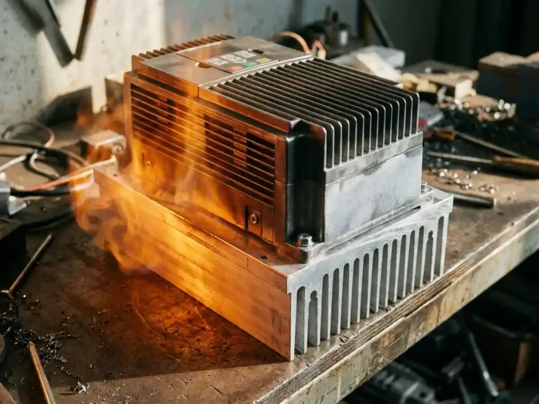
Temperature is one of the most consequential variables in power electronics, and motor controllers are no exception. Every time a controller switches current to drive a motor, heat is generated inside the housing. How well that heat is managed, and how consistently operating temperatures stay within acceptable limits, directly shapes how long the controller will perform reliably. Understanding the relationship between motor controller temperature and long-term reliability is not just useful for engineers; it matters to anyone specifying or operating electric vehicles and industrial equipment where unplanned downtime carries real costs.
The physics are straightforward: heat accelerates the chemical and mechanical processes that cause components to wear. What makes thermal management genuinely complex is that heat does not affect all components equally, and the damage it causes often accumulates invisibly over months or years before a failure becomes apparent.
How heat builds up inside a motor controller
Heat in a motor controller originates primarily from power losses in the switching devices, most commonly MOSFETs or IGBTs, and in the passive components such as capacitors, inductors, and bus bars that carry high currents. Every switching event produces a small amount of resistive loss, and at the switching frequencies required for smooth motor control, those losses add up quickly.
The problem compounds when the thermal path from the heat source to the ambient environment is inefficient. If heat cannot travel away from the switching devices fast enough, junction temperatures rise. In a compact controller housing, heat from multiple sources can accumulate in a confined space, creating hotspots that exceed the thermal ratings of nearby components even when the overall controller temperature appears manageable from the outside.
The link between temperature and component degradation
Elevated temperature accelerates degradation through several distinct mechanisms. Electrolytic capacitors, which are common in motor controllers for filtering and energy storage, lose electrolyte over time, and that process speeds up significantly at higher temperatures. A capacitor operating consistently near its maximum rated temperature may have a service life measured in hundreds of hours rather than tens of thousands.
Solder joints are equally vulnerable. Repeated thermal cycling, where components heat up during operation and cool down when the system is idle, causes the solder to expand and contract. Over time, this mechanical fatigue cracks the joint, increasing resistance and eventually causing intermittent or complete electrical failure. The faster and wider the temperature swings, the sooner joint fatigue becomes a problem. MOSFETs and other semiconductors face a related risk: sustained high junction temperatures reduce carrier mobility and can cause gradual parameter drift, meaning the device no longer switches as cleanly or efficiently as it did when new.
Why thermal management design determines controller lifespan
Given how directly temperature drives degradation, the thermal architecture of a controller is arguably the most important factor in its long-term reliability. A controller with excellent thermal management will sustain its rated performance across years of demanding operation; one with a poor thermal path will degrade faster even if every other aspect of its design is sound.
Effective thermal management involves more than attaching a heatsink. The thermal resistance at every interface, from the semiconductor junction through the substrate, through the mounting surface, and into the ambient environment, must be minimised. This is where substrate technology becomes decisive. Conventional FR4 PCBs conduct heat poorly, which means the thermal path from a MOSFET’s package to any external heatsink passes through a material that actively impedes heat flow. Metal-core substrates address this by replacing the insulating core with a thermally conductive metal layer, dramatically reducing the resistance between the component and the heatsink. The practical result is lower steady-state junction temperatures for the same operating load, which translates directly into longer component life.
Operating conditions that put controllers at highest thermal risk
Not all operating profiles stress a controller equally. Sustained high-current operation, such as a forklift repeatedly lifting maximum loads with minimal rest time, keeps power dissipation high and gives the controller little opportunity to shed accumulated heat. High ambient temperatures compound this: a controller operating in a warm industrial environment or under direct sunlight starts from a higher baseline, leaving less thermal headroom before component limits are approached.
Frequent stop-start cycles create a different but equally damaging pattern. Each acceleration event demands a burst of current, generating a spike in heat, followed by a partial cool-down. The cumulative effect of many such cycles on solder joints and semiconductor packages can be more damaging than a sustained moderate load, because it is the range and rate of temperature change that drives mechanical fatigue rather than the absolute peak alone. Electric vehicle controllers used in applications like AGVs and scissor-lifts face this pattern continuously throughout a working shift.
Indicators that thermal stress is shortening controller life
Thermal stress rarely announces itself with an immediate failure. More often, it manifests through gradual changes in behaviour that are easy to overlook until the damage is already significant. A controller that increasingly triggers its thermal protection cutout under loads it previously handled without issue is a clear sign that something in the thermal path has degraded, whether through a failing heatsink interface, blocked ventilation, or component drift.
Subtle performance changes are also worth attention. Increased motor noise or roughness at low speeds can indicate that capacitors are losing capacitance, affecting the quality of current waveforms. Unexpected variation in motor speed or torque response under consistent load may point to parameter drift in the switching devices. These symptoms do not always have thermal causes, but when they appear in a controller with a known history of high-temperature operation, thermal degradation is a reasonable first hypothesis. Catching these signs early, before a hard failure occurs, gives operators the opportunity to address root causes rather than replace the entire unit.
How DMC addresses thermal risk in motor controller design
DMC’s approach to long-term power electronics reliability is built around eliminating thermal risk at the design level rather than managing its consequences after the fact. The SuperSigma2 and Sigma2N controller ranges incorporate DMC’s proprietary IMS (Insulated Metal Substrate) technology, which allows SMD MOSFET power devices to be mounted directly onto a metal PCB. This removes the high-resistance thermal barrier that conventional substrates introduce, keeping junction temperatures significantly lower under equivalent operating loads.
The practical benefits of this approach include:
- Lower steady-state operating temperatures for the switching devices, extending component service life
- Reduced thermal cycling stress on solder joints, limiting mechanical fatigue over time
- More consistent performance across a wide range of ambient conditions and duty cycles
- Support for nominal battery voltages from 24V to 108V and peak powers up to 60kW, without compromising thermal headroom
DMC’s controllers also offer fully automated motor and sensor tuning, which ensures the controller operates the motor efficiently from the outset, avoiding unnecessary heat generation that comes from poorly optimised control parameters. If thermal management in your application is a concern, or if you are specifying a controller for a demanding duty cycle, contact DMC directly to discuss which solution fits your operating profile.
Related Articles
- Why do aerial work platforms have very different drive and lift duty cycles?
- How do traction, steering and hydraulic loads compete for power in a battery-powered machine?
- Can you manually tune a motor controller without a PC?
- BLDC vs PMSM controllers: are they the same thing?
- When should you not use sensorless control?