
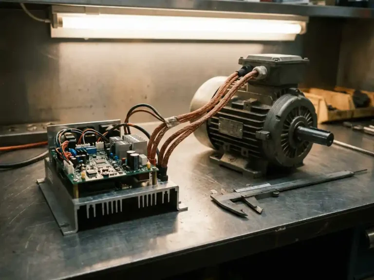
Yes, the motor must be compatible with the controller. Running a mismatched combination risks poor performance at best and permanent hardware damage at worst. Compatibility covers several factors: motor type, voltage rating, sensor interface, and power rating. The sections below work through each of those factors in turn.
What makes a motor and controller electrically compatible?
A motor and controller are electrically compatible when the controller can generate the correct waveform and voltage for the motor type, the power ratings align, and the communication interface between motor sensors and controller inputs matches. All four of those conditions need to be met simultaneously, not just one or two.
Voltage is the most obvious check: the controller’s operating voltage range must cover the nominal battery voltage the system runs on. Power rating matters just as much. A motor capable of drawing 20 kW peak should be paired with a controller rated to supply at least that much without operating continuously at its ceiling. Running a controller at or near its peak rating for extended periods shortens its service life.
Beyond voltage and power, the control method has to suit the motor’s design. AC induction motors, permanent magnet synchronous motors (PMS), and interior permanent magnet (IPM) motors each require different control algorithms. A controller built only for DC series motors cannot drive an AC induction motor, regardless of whether the voltage numbers happen to match.
What motor types are supported by AC motor controllers?
AC motor controllers are designed to drive AC induction motors and permanent magnet AC (PMAC) motors, which includes both surface-mount PMS types and interior permanent magnet (IPM) designs. These three motor types share the same fundamental requirement for variable-frequency AC drive output, which is what distinguishes an AC controller from a DC one.
The practical difference between the three types lies in rotor construction and how the magnetic field is generated. In an AC induction motor, the rotor field is induced by the stator current, so the motor requires a controller that can manage slip frequency. PMS and IPM motors use permanent magnets in the rotor, which changes the control strategy to field-oriented control (FOC). A controller that supports all three types needs to switch between these strategies based on the motor it detects during setup.
DC motors, including series-wound, shunt, and separately excited types, are outside the scope of AC controllers entirely. If you are working with a mixed fleet where some vehicles run DC motors and others run AC, the controllers are not interchangeable between those groups.
Does motor voltage rating have to match the controller’s battery voltage?
The motor’s voltage rating does not need to match the battery voltage exactly, but the controller’s operating voltage range must cover the battery voltage, and the motor must be rated to handle the voltages the controller will apply to its windings. The controller acts as the intermediary, so the critical match is between battery voltage and controller input range, not between battery and motor directly.
In practice, AC motor controllers regulate the output to the motor using pulse-width modulation, which means the motor sees a controlled waveform rather than raw battery voltage. A motor rated for a certain winding voltage should be operated within that range to avoid insulation stress. Significantly overvolting a motor’s windings, even through a controller, degrades winding insulation over time.
When selecting a motor for a specific battery voltage, check the motor’s nameplate voltage against the controller’s output capability at that battery voltage. If the motor was designed for a 48V system and the battery is 80V, verify that the controller’s modulation depth and output settings can limit the effective motor voltage appropriately, or choose a motor wound for the higher voltage.
How does motor sensor type affect controller compatibility?
The sensor interface is one of the most common sources of incompatibility in motor-controller pairing. Controllers are designed to accept specific sensor signal types, and if the motor’s position sensor outputs a signal the controller cannot read, the controller cannot determine rotor position and will not run the motor correctly.
The most common sensor types in electric vehicle and industrial applications are Hall effect sensors, resolvers, and incremental encoders. Hall sensors output simple digital signals and are widely used in PMAC motors. Resolvers provide continuous analog position data and are more robust in harsh environments. Encoders offer high-resolution digital position feedback. Each requires a different input circuit and decoding method on the controller side.
Sensorless control removes the sensor dependency entirely by estimating rotor position from back-EMF and current measurements. This is a valid approach in some applications, but it has limitations at very low speeds and during startup, which is why it is generally avoided for traction applications where smooth, low-speed torque control is required.
Before commissioning, confirm that the sensor type fitted to the motor appears in the controller’s supported sensor list. Attempting to run with a mismatched sensor input typically results in erratic speed control or a fault condition rather than outright hardware damage, but the system will not function correctly until the mismatch is resolved.
What happens if you run an incompatible motor with a controller?
Running an incompatible motor with a controller produces outcomes ranging from immediate fault shutdown to gradual thermal damage, depending on the nature of the mismatch. The controller may detect the incompatibility and protect itself, or it may attempt to drive the motor and cause damage to one or both components in the process.
A voltage mismatch where the battery exceeds the controller’s rated input is the most immediately dangerous scenario. Overvoltage can destroy the controller’s power switching devices in a single event. A motor type mismatch, such as connecting a DC series motor to an AC controller, will typically result in a fault code and no motor output rather than hardware damage, since the controller cannot produce a usable waveform for that motor type.
Sensor mismatches usually produce unstable or absent torque output. The motor may jerk, hunt, or fail to start. In some cases, if the controller attempts to drive the motor without valid position feedback, it can apply incorrect phase currents that cause the motor to overheat. Thermal damage to motor windings is cumulative and may not be immediately apparent.
Power rating mismatches cause gradual degradation. A controller undersized for the motor load will run hot, reducing the lifespan of its switching devices and capacitors. Over time, this shows up as intermittent faults, reduced peak performance, and eventually component failure.
How is motor-controller compatibility verified during commissioning?
Compatibility verification during commissioning involves confirming the electrical parameters, running the controller’s setup or autotuning routine, and validating the result under controlled load conditions. This sequence catches mismatches that are not obvious from the nameplate data alone.
The first step is a documentation check: compare the motor’s datasheet against the controller’s specification sheet for voltage range, power rating, motor type, and sensor interface. Any mismatch identified at this stage should be resolved before the system is powered up.
Once the hardware is confirmed, the controller’s autotuning function measures the motor’s electrical characteristics directly, including winding resistance, inductance, and, for PMAC motors, the back-EMF constant. This process identifies motors that are nominally compatible but have winding parameters outside the range the controller can handle effectively. It also sets the current control loops to values appropriate for the specific motor rather than relying on generic defaults.
After autotuning, a low-load or no-load run confirms that speed response, direction, and sensor feedback are all working correctly before the system is placed under full operating conditions. Any residual faults or unusual behavior at this stage should be investigated rather than cleared and ignored.
How the SuperSigma2 handles motor-controller compatibility
The SuperSigma2 motor controller from DMC is built around the compatibility challenges described above. It supports AC induction, PMS, and IPM motors within a single platform, operating on battery voltages from 24V to 108V with nominal power up to 30 kW and peak power up to 60 kW. Key features that directly address compatibility include:
- Fully automated motor and sensor tuning that measures each motor’s actual electrical parameters at commissioning, removing dependence on manual data entry
- Support for multiple sensor types, with sensorless control available for applications where sensors are impractical
- IMS (Insulated Metal Substrate) thermal management, which keeps power devices cooler under load and reduces the risk of thermal failure when operating near rated limits
- Dual-processor architecture with CANopen support for integration into vehicle control networks
If you are specifying or commissioning a system and need to confirm whether a particular motor will work with the SuperSigma2, contact DMC directly with the motor datasheet. The engineering team can confirm compatibility before hardware is ordered.
Related Articles
- What happens if you run a motor in field weakening for too long?
- How do steering and traction systems interact in a battery-powered vehicle?
- How does FOC improve torque response compared to older control methods?
- How do you design for good thermal management in a motor controller?
- What is the difference between a motor driver and a motor controller?