
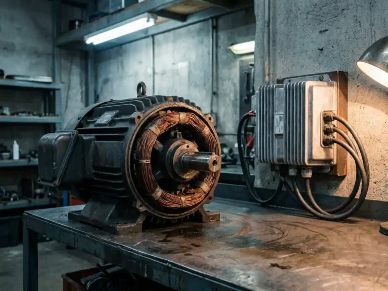
Motors need controllers because an electric motor left to run directly from a battery or power supply has no way to regulate how fast it spins, how much torque it delivers, or when it stops. Without a controller, the motor draws uncontrolled current, can overheat, stall, or fail, and has no safe way to shut down. For anyone responsible for an AGV, forklift, conveyor, or custom drive, that means unplanned downtime, burnt windings, and costly repairs. A controller sits between the power source and the motor and decides how much energy reaches the windings at any moment. That is the core of what the term controller meaning covers in practice.
A motor controller is an electronic device that monitors and controls the direction, speed, torque, and other operating functions of an electric motor, in addition to providing motor protection. In plain terms, it is the electronic device that controls an electric motor so that the motor behaves predictably instead of simply running at whatever the supply allows. This article explains what happens without a motor controller, how regulation and protection work, which controller types exist, where they are used, and how to choose the right one. If you already know your application, you can talk to the DMC team at any point.
Risks of Running a Motor Without a Controller
Overheating
Without a controller, nothing limits the current the motor draws. Sustained overcurrent heats the windings faster than they can shed heat, and there is no thermal monitoring to reduce the load or cut the supply. Insulation degrades with every hot cycle, and the motor can fail well before its rated life.
Stalling and Blocking
When a load blocks the rotor, the motor draws very high current while producing no motion. With direct supply, nothing limits that current and nothing detects the stall. The windings take the full load until something burns out or the power source trips.
Premature Failure
Every direct start produces a large inrush current and an abrupt mechanical shock to the drivetrain. Repeated over time, this wears windings, bearings, couplings, and gearboxes. The result is more breakdowns and shorter service intervals than a controlled start would cause.
No Safe Shutdown
A directly supplied motor has no fault detection, so there is no managed way to stop when something goes wrong. A fault can spread from the motor to the wiring and the power source before anyone notices. A controller removes this gap, and its functions are covered in the sections below.
What happens to a motor without a controller?
A motor connected directly to a power source runs at an uncontrolled speed determined entirely by the supply voltage and the motor’s own electrical characteristics. There is no current limiting, no ramp-up, and no feedback mechanism. The motor will draw its maximum possible current at startup, generating heat and mechanical stress that the windings and bearings are not designed to sustain continuously.
In practical terms, this means the motor either stalls under load, overheats within minutes, or accelerates to a fixed speed with no ability to adjust. For battery-driven vehicles or industrial platforms, that makes the motor functionally useless. A forklift that cannot modulate lift speed, or an AGV that cannot vary traction force, cannot do its job safely. The controller is what converts a raw power source into a controllable drive system.
How does a motor controller regulate speed and torque?
A motor controller regulates speed and torque by varying the voltage and current delivered to the motor, typically through pulse-width modulation (PWM). The controller switches power on and off at high frequency, and by adjusting the ratio of on-time to off-time, it effectively controls the average power reaching the motor. This allows fine-grained control over both rotational speed and the force the motor produces.
Torque control and speed control are closely linked but operate through different feedback loops. Speed control monitors the motor’s rotational output and adjusts PWM duty cycle to maintain a target speed. Torque control monitors current draw, since torque in an electric motor is directly proportional to current, and limits or adjusts the current to deliver the required mechanical output without exceeding safe thresholds.
Modern controllers for AC induction and permanent magnet motors add a layer called field-oriented control (FOC), which manages the motor’s magnetic field vectors directly. This allows smooth, efficient operation across a wide speed range, including at very low speeds where simpler control methods lose accuracy. The result is precise, responsive drive behaviour that direct connection to a power supply could never replicate.
What types of motors require a controller?
Virtually every motor used in a variable-speed or variable-load application requires a controller. DC brushed motors, AC induction motors, and permanent magnet synchronous motors (PMSM, including both surface-mounted PMS and interior permanent magnet IPM types) all require dedicated control electronics to operate correctly in real-world conditions.
Brushed DC motors are the simplest case. A basic speed controller can manage them with straightforward voltage adjustment. AC induction motors are more complex because they require a controlled frequency and voltage to set the synchronous speed of the rotating magnetic field. PMAC motors (PMS and IPM types) are the most demanding, requiring precise knowledge of rotor position to maintain efficiency and avoid demagnetisation.
In electric vehicles and industrial platforms, the motor type dictates the controller architecture. A pump motor on a scissor-lift has different control requirements than a traction motor on an AGV, even if both are permanent magnet machines. The motor controller must be matched to the motor’s electrical characteristics, the application’s load profile, and the battery voltage range in use. Not sure which combination fits your motor? Send DMC your motor and battery specifications and get a recommendation for your setup.
What’s the difference between a motor controller and a motor driver?
A motor driver is the power stage that physically switches current to the motor windings. A motor controller is the broader system that includes the driver but also handles logic, feedback processing, protection functions, and communication. The driver executes commands; the controller decides what those commands should be.
In many products, the two are integrated into a single unit, which is why the terms are often used interchangeably. The distinction matters most when troubleshooting or designing a system from components. A driver without a controller has no intelligence. A controller without a capable driver stage cannot deliver the current levels a traction or lift motor demands.
For field engineers, the practical implication is that replacing a driver stage does not necessarily fix a control problem, and a controller firmware issue will not be resolved by swapping power components. Understanding which layer of the system is responsible for a given behaviour saves significant diagnostic time on site.
How does a controller protect a motor from damage?
A motor controller protects a motor by monitoring key operating parameters in real time and intervening before those parameters exceed safe limits. The primary protection mechanisms are overcurrent limiting, overtemperature shutdown, undervoltage lockout, and stall detection. Each targets a specific failure mode that would otherwise shorten motor life or cause immediate damage.
Overcurrent protection prevents the motor windings from carrying more current than they can dissipate as heat. If a load stalls the motor or a fault causes a current spike, the controller reduces or cuts the drive signal before the windings reach a damaging temperature. Overtemperature protection monitors both the controller’s own power stage and, where a sensor is fitted, the motor itself.
Undervoltage lockout prevents the controller from operating when battery voltage drops below a threshold where it can no longer guarantee correct switching behaviour. Running a PWM stage at insufficient supply voltage can produce erratic output that damages motor windings or causes unpredictable mechanical behaviour. Stall detection identifies when the motor is drawing high current without producing rotation and reduces drive output accordingly.
Taken together, these protections address the overheating, stalling, and unsafe shutdown risks described above. In practice, that means fewer motor replacements, fewer unplanned stops, and a drive you can rely on.
Common Types of Motor Controllers
Brushed DC Motor Controllers
Brushed DC controllers adjust the voltage or PWM duty cycle applied to the motor, and many also limit current. They suit simple, cost-sensitive drives with a fixed commutation scheme built into the motor itself. Typical uses include small pumps, simple actuators, and basic tools.
Brushless DC (BLDC) Motor Controllers
A BLDC motor has no mechanical brushes, so electronic commutation requires a controller to switch the phases in the right sequence. The controller reads rotor position from sensors or estimates it without them, then times each phase accordingly. BLDC controllers are common in fans, e-mobility, and compact industrial drives where efficiency and long life matter.
Stepper Motor Drivers
Stepper drivers energize the motor windings in discrete steps, so the shaft moves in precise, repeatable increments. They suit positioning tasks such as 3D printers, small CNC machines, and laboratory equipment. Many drivers add microstepping and current control to smooth motion and reduce heating.
AC Motor Drives and Variable Frequency Drives
AC drives, including variable frequency drives (VFDs), vary the frequency and voltage supplied to an AC induction or permanent magnet motor. This sets the motor speed and allows controlled acceleration and deceleration. They are widely used as an industrial motor controller for pumps, fans, and process machinery.
Choosing the type depends on the motor, the load, the precision required, and the operating environment.
Where Motor Controllers Are Used: Industrial Drives and Conveyor Systems
Conveyor Motor Controllers
A conveyor motor controller provides soft start and stop, so products are not jolted on the belt and the mechanics are spared repeated shock. It allows adjustable belt speed to match the process and handles changing loads as the belt fills or empties. When several drives run in one line, controllers can synchronize them so the belt sections move together.
Industrial Automation and Drive Systems
In automated plants, controllers deliver the process precision that repeatable manufacturing needs. Controlled acceleration and speed also support better energy efficiency than running a motor at full output all the time. Built-in fault diagnostics help maintenance teams find problems early, which means fewer breakdowns and smoother operation.
Robotics and Maker Projects
Makers and developers often pair a small BLDC or DC motor with a driver board and a development board. This setup is enough to learn speed control, direction control, and basic feedback on a bench before moving to larger drives. The same principles carry over to professional robotics and mobile platforms.
Digital Motor Control With a Microcontroller
In digital motor control, a microcontroller such as a device from the STM32 family acts as the control unit. It runs the control loop: it reads feedback, compares it with the target, and updates the output many times per second. It also generates the PWM signals that set the power delivered to the motor.
A microcontroller alone cannot drive a motor directly, because its pins cannot supply the current a motor needs. A power stage or driver sits between the microcontroller and the motor and switches the actual motor current. Current and position or speed feedback close the loop, so the controller can limit torque, hold speed, and react to faults.
The main building blocks of such a design are:
- Microcontroller running the control loop and PWM generation
- Gate driver or power stage that switches the motor current
- Current sensing for torque control and overcurrent protection
- Speed or position sensor for closed-loop control
- Protection logic for overtemperature, undervoltage, and fault handling
Building this from scratch is a good way to learn, but for traction or lift drives at higher voltages and power levels, a proven, ready-made controller saves development time and commissioning risk.
How to Choose the Right Motor Controller
The right controller depends on a handful of criteria. Work through the following checklist before comparing products:
- Motor type: brushed DC, BLDC, stepper, AC induction, or permanent magnet motors each need a matching controller.
- Voltage and current rating: the controller must cover the supply voltage and the continuous and peak current the motor will draw.
- Required control mode: decide whether the application needs speed, torque, or position control.
- Feedback and communication interfaces: check sensor support and the interfaces needed to connect to the wider system.
- Protection features: look for overcurrent, overtemperature, undervoltage, and stall protection.
- Operating environment: temperature, vibration, moisture, and dust all affect which controller is suitable.
Once these points are clear, the choice narrows quickly. DMC offers motor controller solutions for demanding drive systems, and the SuperSigma2 range below is one example. If you have your motor type, battery voltage, and power requirement at hand, you can contact DMC for a configuration recommendation, or browse the product range to compare options yourself.
When should a motor controller be recalibrated or retuned?
A motor controller should be recalibrated or retuned whenever the motor is replaced, when the application’s load profile changes significantly, or when performance has drifted noticeably from its original commissioning baseline. Tuning parameters are set to match specific motor characteristics, and those parameters become inaccurate if the motor or its operating conditions change.
Common triggers for retuning include motor rewinding or replacement with a different unit, changes to the mechanical drivetrain such as a new gearbox ratio, and battery pack replacement with a different chemistry or capacity. Even gradual wear in the motor’s bearings or windings can shift electrical characteristics enough to warrant a fresh calibration pass.
For sensorless control modes, retuning is especially important after any motor change because the controller’s model of the motor’s back-EMF behaviour is central to its speed estimation. With sensored systems, a recalibration check after sensor replacement or rewiring catches any offset errors before they cause control instability in service. Controllers with automated tuning make this routine far less time-consuming, as described below.
How the SuperSigma2 addresses motor control requirements
DMC’s SuperSigma2 range is built specifically for the control demands described throughout this article. It handles AC induction, PMS, and IPM motor types within a single platform, operating across nominal battery voltages from 24V to 108V with nominal power up to 30 kW and peak power up to 60 kW. Key capabilities that directly address common field requirements include:
- Fully automated motor and sensor tuning: removes manual parameter entry errors during commissioning and retuning after motor replacement, so you get a drive running faster.
- Sensorless control capability: suits applications where encoder or resolver feedback is impractical.
- Dual processor architecture with full CANopen support: enables real-time diagnostics and integration with vehicle management systems, so faults are visible before they become failures.
- IMS (Insulated Metal Substrate) thermal management: mounts power switching devices directly onto a metal PCB for more effective heat dissipation, reducing thermal stress on the power stage during sustained high-load operation.
These features make the SuperSigma2 relevant across traction, pump, and power-steering applications in AGVs, forklifts, boom-lifts, and marine platforms.
Next step: discuss your application with DMC
Tell the DMC team about your motor, battery voltage, and application, and they can help you assess whether the SuperSigma2 fits your drive. To discuss a specific application or request technical documentation, contact the DMC team directly. For a full overview of available configurations, visit the DMC products page.
Related Articles
- How big of a battery do I need to run a 3000W inverter?
- What happens to a scissor lift electrical system while the platform is being raised?
- How does FOC improve torque response compared to older control methods?
- What is a brushless motor controller, and how does it work?
- What is IMS substrate in a motor controller?