
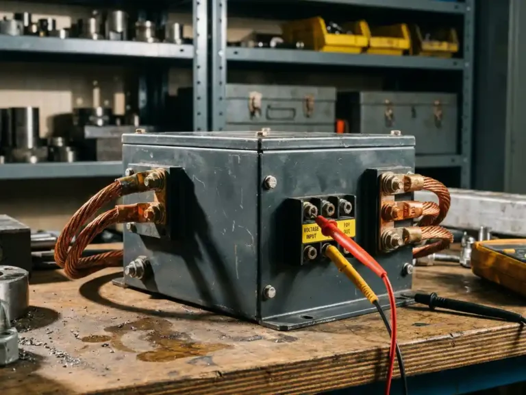
Voltage rating is one of the first specifications a field service engineer checks when selecting or commissioning a motor controller. Get it wrong and the consequences range from poor performance to permanent damage. Yet the spec sheet number alone rarely tells the full story. Understanding what voltage ranges mean in practice, how they relate to battery pack configuration, and where nominal and peak figures diverge is essential knowledge for anyone integrating controllers into electric vehicles or industrial platforms.
This article walks through the key voltage considerations that shape motor controller selection, from battery architecture through to commissioning checks in the field.
How battery voltage determines controller selection
The battery pack voltage defines the operating environment the controller must survive and perform within. Controllers are designed around specific voltage windows, and operating outside those windows, even briefly, risks tripping protection circuits or causing component stress that shortens service life.
Battery packs in electric vehicles and industrial machines are built from cells arranged in series. Adding cells in series raises the nominal pack voltage. A 48V system might use 40 lithium cells in series; a 72V or 96V system simply extends that chain. The controller must be rated to handle not just the nominal pack voltage but also the elevated voltage that appears when the pack is fully charged. A nominally 48V lithium pack can sit at 54V or higher when fresh off the charger, which means a controller rated to exactly 48V would be operating at the edge of its tolerance from the moment the vehicle leaves the charging station.
Voltage ranges across common EV and industrial applications
Different application categories have settled around recognizable voltage bands, shaped by the balance between energy density, cable sizing, safety thresholds, and legacy infrastructure.
Light-duty pedestrian vehicles, golf cars, and smaller AGVs typically operate on 24V, 36V, or 48V systems. These voltages keep wiring manageable, reduce insulation requirements, and stay within ranges considered relatively safe for routine maintenance. Counterbalance forklifts, larger reach trucks, and heavy-duty platform vehicles more commonly run at 48V, 72V, or 80V, where higher voltage allows the same power to be delivered at lower current, reducing cable losses and heat in the drivetrain. At the upper end, high-capacity forklifts, boom lifts, and some hybrid industrial platforms push into the 80V to 108V range, where the power demands of traction and auxiliary systems justify the additional complexity.
Marine and off-highway applications vary more widely, since pack configuration is often dictated by available battery modules rather than a standardized architecture. Controllers that span a broad voltage window give integrators more flexibility when battery sourcing changes between production runs.
AC induction vs. PMAC motors: voltage compatibility differences
Motor type affects how voltage interacts with controller design, and this matters when specifying a replacement or upgrade.
AC induction motors generate torque by inducing current in the rotor. The controller must produce a variable-frequency, variable-voltage AC output from the DC bus, and the relationship between bus voltage and achievable motor speed is direct. At lower bus voltages, the maximum achievable motor speed before field weakening is reached sooner, which can limit top-end performance in traction applications.
PMAC motors, including surface-mounted PMS types and interior permanent magnet (IPM) designs, have higher back-EMF for a given speed because the rotor magnets contribute to the flux. This means the controller needs sufficient bus voltage to overcome that back-EMF and push current through the motor windings at the required operating point. In practical terms, a PMAC motor running at high speed on a low bus voltage may see reduced torque capability compared to the same motor on a higher voltage pack. Engineers specifying a controller for a PMAC application should verify that the battery pack voltage, at its minimum state of charge, still provides adequate headroom above the motor’s back-EMF at maximum operating speed.
Peak vs. nominal voltage: what the specs actually mean
Nominal voltage is the reference point manufacturers use to describe a controller’s operating range. It corresponds to the midpoint or typical operating voltage of the intended battery chemistry rather than the maximum voltage the pack can produce.
Peak voltage, sometimes listed as maximum input voltage in datasheets, is the upper limit the controller’s power stage can safely handle. For lead-acid systems, the gap between nominal and peak is relatively modest. For lithium chemistries, particularly LFP and NMC packs, the fully charged voltage can sit meaningfully above nominal, and this gap needs to be accounted for at the selection stage.
The minimum voltage threshold matters equally. As a battery discharges, pack voltage drops. If it falls below the controller’s minimum operating voltage, the unit may cut out or behave unpredictably. In traction applications, this low-voltage cutoff is often tunable, allowing the engineer to set a threshold that protects the battery from deep discharge while giving the operator adequate warning before shutdown.
Matching controller voltage spec to your system during commissioning
Commissioning is the point where voltage compatibility moves from a datasheet exercise to a live verification. The first check is measuring actual pack voltage at full charge and confirming it sits within the controller’s rated input range with margin to spare. The second is confirming the minimum discharge voltage of the pack stays above the controller’s lower threshold under the load conditions the application demands.
Where battery management systems are present, it is worth verifying that the BMS voltage limits and the controller voltage limits are aligned. A BMS set to disconnect at 20% state of charge may produce a pack voltage that still exceeds the controller’s minimum, but a BMS configured for a different chemistry or cell count could create a mismatch that causes nuisance shutdowns in service.
Wiring resistance also plays a role. Under heavy load, voltage at the controller terminals can drop several volts below the measured pack voltage due to cable resistance and connector losses. In high-current applications, measuring voltage directly at the controller input under load, rather than at the battery terminals, gives a more accurate picture of the operating conditions the controller actually experiences.
How the SuperSigma2 handles voltage range requirements
DMC’s SuperSigma2 controller range is built to cover the voltage band that spans the majority of electric vehicle and industrial applications in a single platform. Key specifications relevant to voltage selection include:
- Nominal battery voltage from 24V to 108V, covering light-duty through heavy-duty traction systems
- Compatibility with AC induction, PMS, and IPM motor types from one hardware platform, removing the need to stock separate controllers for different motor technologies
- Fully automated motor and sensor tuning, which includes calibration of voltage-dependent parameters at commissioning rather than requiring manual calculation
- Nominal power up to 30 kW and peak power up to 60 kW, supported by IMS (Insulated Metal Substrate) thermal management that keeps power devices within safe operating temperatures across the voltage range
- CAN Open integration (standard since early 2023) enabling voltage monitoring and protection thresholds to be configured and logged through the vehicle network
For engineers specifying a controller across a mixed fleet or designing a platform that may use different battery configurations in different markets, the SuperSigma2’s broad voltage window reduces the number of part numbers to manage. To discuss specific voltage requirements for your application, contact the DMC team directly.
Related Articles
- What is field weakening and when do you need it?
- How does repeated acceleration affect the electrical system of mobile equipment?
- Why can steering require high torque even at very low vehicle speed?
- Can you manually tune a motor controller without a PC?
- How do you design for good thermal management in a motor controller?