
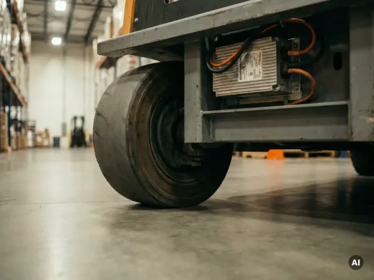
Machine mass directly shapes traction system behaviour by determining how much torque the motor must produce to accelerate, decelerate, and hold speed under varying load conditions. Heavier machines demand more torque at low speeds, extend the time required to reach target velocity, and place greater thermal stress on both the motor and its controller. The sections below work through each of these effects in detail, from inertia and ramp control through to braking, thermal management, and parameter tuning.
How does vehicle inertia affect motor torque demand?
Vehicle inertia determines the baseline torque a traction motor must produce to change the machine’s velocity. The greater the machine mass, the more torque is required to achieve the same rate of acceleration. This relationship is direct and linear: double the mass, and you need roughly double the torque to reach the same speed in the same time.
In practical terms, this means a forklift operating at full rated payload requires significantly more current from the controller during acceleration than the same machine running unloaded. The motor must overcome not just rolling resistance and gradient, but also the rotational inertia of the drivetrain combined with the translational inertia of the entire vehicle mass. When the load sits near the upper end of the machine’s rated capacity, torque demand at launch can approach or briefly exceed the motor’s continuous rating, pushing the system into peak operating territory.
For engineers specifying motor controllers, this matters because the controller’s current limits must be sized not for the average operating point but for the worst-case inertial demand. A machine that spends most of its time lightly loaded but occasionally moves at full capacity needs a controller capable of sustaining peak torque long enough to complete each acceleration event without triggering overcurrent protection prematurely.
Why does machine mass change the way a controller handles acceleration ramps?
Acceleration ramp settings control how quickly the controller increases motor current and speed reference after a drive command. When machine mass increases, a fixed ramp rate that worked well at low payload can produce wheel slip, drivetrain shock, or instability, because the rate of speed change relative to the available traction force becomes mismatched with the vehicle’s actual inertia.
A lighter machine responds quickly to a given ramp rate, so a relatively steep ramp keeps the machine responsive without exceeding traction limits. The same ramp applied to a heavily loaded machine can demand more torque than the tyres or drive surface can support, causing the driven wheels to lose grip momentarily. On the other hand, a ramp set conservatively for the heaviest load condition will feel sluggish on an unloaded machine, reducing productivity.
This is why many modern traction controllers allow independent adjustment of acceleration and deceleration ramp times, and why some applications benefit from load-dependent ramp profiles. Where the payload is known or measurable, the ramp can be adapted accordingly. Where it varies unpredictably, the ramp must be tuned to a compromise that prevents instability at full load while remaining acceptable at minimum load.
What happens to braking and regeneration performance as load mass increases?
As load mass increases, both the energy that must be absorbed during braking and the forces acting on the drivetrain during deceleration rise proportionally. For regenerative braking, this means more energy is available to return to the battery, but the rate at which that energy can be absorbed is limited by the battery’s charge acceptance and the controller’s current-handling capacity.
A heavily loaded machine travelling at operational speed carries considerably more kinetic energy than the same machine unloaded. If the deceleration ramp is set to bring the machine to rest in the same distance regardless of load, the regenerative braking current required at full payload will be much higher. If the controller cannot sustain that current level, it will either limit the braking force, extending stopping distance, or switch to mechanical braking to compensate.
There is also a stability consideration. Aggressive regenerative braking on a high-inertia machine can cause the driven wheels to lock or slip if the braking torque exceeds the available traction. For machines that operate across a wide payload range, such as counterbalance forklifts or platform stackers, the braking ramp settings need to account for the heaviest likely load to prevent instability, even if this means slightly longer stopping distances when running light.
How does payload variation affect motor thermal management?
Payload variation directly affects how hard the motor works over a duty cycle, and therefore how much heat it generates. A motor running repeated acceleration and braking cycles at high payload will accumulate heat far faster than the same motor performing the same cycle with minimal load, because the current drawn during each event is substantially higher.
The thermal challenge is not just peak temperature but sustained temperature under repeated loading. A single heavy lift followed by a long idle period may be thermally benign. A sequence of short, high-load cycles with minimal recovery time between them can drive winding and power device temperatures well above safe limits, even if no individual event appears severe in isolation.
Controllers manage this through a combination of thermal modelling and direct temperature sensing. A well-configured system tracks estimated motor temperature based on current history and ambient conditions, and begins reducing available torque before physical damage occurs. However, this protection is only as effective as the accuracy of the thermal model and the quality of the sensor data. For applications where payload varies significantly between shifts or between operators, the thermal model parameters need to reflect the worst-case duty cycle rather than average conditions.
Which traction controller parameters need adjusting for different machine masses?
Several controller parameters interact with machine mass directly, and getting them right requires working from the actual vehicle specification rather than default values. The most significant are current limits, acceleration and deceleration ramp times, and thermal protection thresholds.
- Peak and continuous current limits set the ceiling on torque output. For heavier machines, the peak limit must be high enough to handle inertial demand at launch, while the continuous limit must reflect what the motor can sustain thermally over the expected duty cycle.
- Acceleration and deceleration ramp times need to be long enough to prevent wheel slip and drivetrain shock at full payload, but not so long that the machine feels unresponsive when lightly loaded.
- Regenerative braking current limits determine how aggressively the system recovers energy during deceleration. These must be calibrated to the maximum load condition to avoid instability.
- Thermal model parameters should reflect the motor’s actual thermal characteristics and the machine’s expected duty cycle at full payload, not just average or nominal operating conditions.
Where machines operate across a wide range of payloads, some applications use input signals (from a load sensor or a fleet management system) to switch between parameter sets dynamically. This approach allows the controller to apply conservative ramp rates and current limits at high payload while recovering responsiveness at low payload, without requiring manual reconfiguration.
How the SuperSigma2 handles variable machine mass
DMC’s SuperSigma2 controller range is built to address exactly the kind of load variability described above. Designed for AC induction, PMS, and IPM motors operating from 24V to 108V, with nominal power up to 30 kW and peak power up to 60 kW, the SuperSigma2 gives engineers the headroom to handle high inertial demand at full payload without compromising performance at lighter loads. Key capabilities relevant to machine mass management include:
- Fully automated motor and sensor tuning, which establishes accurate motor parameters as the baseline for current control and thermal modelling
- Independently configurable acceleration and deceleration ramp times, allowing tuning to the specific payload range of each application
- Adjustable peak and continuous current limits to match the motor’s thermal capacity and the machine’s inertial demands
- IMS (Insulated Metal Substrate) technology for superior heat dissipation in the controller itself, supporting sustained operation under high-current, high-load duty cycles
- CANopen integration (standard since early 2023), enabling dynamic parameter adjustment based on external load signals where the application supports it
If you are specifying a controller for a machine where payload variation is a significant design constraint, the SuperSigma2’s combination of flexible parameterisation and thermal robustness makes it a practical starting point. Contact the DMC team to discuss your application requirements and get guidance on parameter configuration for your specific vehicle mass range.
Related Articles
- What is field weakening and when do you need it?
- What does the electric motor actually do in a power-steering system?
- What happens inside an electric drivetrain when a machine begins moving from standstill?
- How does FOC improve torque response compared to older control methods?
- How do you design for good thermal management in a motor controller?