
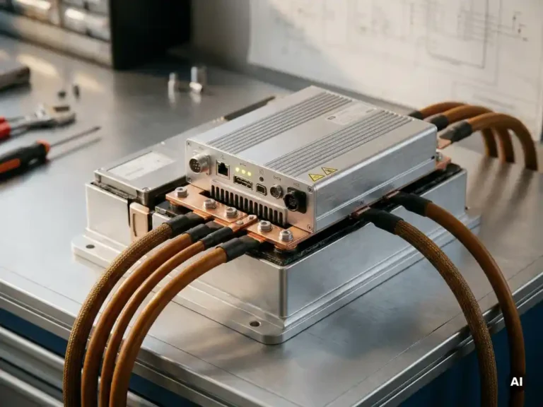
Power inside a battery-powered mobile machine is distributed through a structured electrical architecture that connects the battery pack to multiple subsystems via a central high-voltage DC bus. Each subsystem draws power according to its function, whether that is propulsion, steering, lifting, or onboard electronics. The sections below unpack each layer of that architecture, from the battery terminals to the wheels and back.
What are the main electrical subsystems in a battery-powered mobile machine?
A battery-powered mobile machine typically contains four main electrical subsystems: the energy storage system (the battery pack), the power conversion system (motor controllers and DC/DC converters), the drive and actuation system (traction, pump, and steering motors), and the low-voltage auxiliary system (lighting, sensors, control electronics). These subsystems work together as a coordinated power network rather than independent circuits.
The battery pack sits at the top of the hierarchy, supplying raw DC power at whatever voltage the system is designed around, commonly anywhere from 24V to 96V in industrial platforms. Below it, power conversion hardware conditions that voltage and delivers it in the right form to each load. Motor controllers regulate power to the drive motors, while DC/DC converters step down voltage for the onboard electronics that need a stable, lower supply. A battery management system (BMS) monitors the pack continuously, tracking cell voltages, temperatures, and state of charge to keep the whole system within safe operating limits.
In machines with multiple driven axes, such as a forklift with separate traction and hydraulic pump motors, each motor typically has its own dedicated controller. This separation gives the system designer precise control over each axis independently, which is important for both performance tuning and fault isolation.
How does power flow from the battery to the drive motor?
Power flows from the battery pack through a main contactor, along the DC bus to the motor controller, and then out as conditioned three-phase AC (or switched DC, depending on motor type) to the drive motor. The motor controller is the active element in this chain: it converts the fixed battery voltage into a variable-frequency, variable-voltage output that determines motor speed and torque.
The main contactor acts as the system’s primary switch, connecting and disconnecting the battery from the rest of the power circuit. Pre-charge resistors are typically placed in parallel with the contactor to limit the inrush current that would otherwise spike when capacitors inside the controller charge up at power-on. Without pre-charge, that inrush can weld contactor contacts or stress capacitor banks over time.
Once the contactor closes and the bus capacitors are charged, the motor controller begins switching its power transistors (MOSFETs or IGBTs) at high frequency to synthesize the output waveform. The switching pattern is governed by the controller’s firmware, which executes the motor control algorithm many thousands of times per second. The result is a smooth, controllable torque output despite the motor seeing what is fundamentally a pulsed voltage.
What is the DC bus and why does it matter?
The DC bus is the main high-voltage rail that connects the battery pack to all power-consuming subsystems in the machine. It is the electrical backbone of the power distribution system. Its voltage level sets the operating point for every device connected to it, and its stability directly affects the performance and reliability of the motor controllers, converters, and any other power electronics on the platform.
Bus voltage is not perfectly stable in practice. When a motor accelerates hard, it draws a large current pulse that can pull the bus voltage down momentarily. When a motor brakes regeneratively, it pushes current back onto the bus, raising the voltage. Both conditions must be managed. Motor controllers include bulk capacitance on their input stages to buffer these transients and keep the bus voltage within acceptable bounds during dynamic events.
The DC bus voltage also determines how much power can be delivered for a given current. Higher bus voltages allow the same power to be transferred at lower currents, which reduces resistive losses in cables and connectors. This is why larger or more powerful machines tend to operate at higher nominal voltages, while compact low-power platforms can work efficiently at 24V or 48V.
How are auxiliary systems powered in a battery-powered machine?
Auxiliary systems, such as lighting, horn, sensors, display screens, and control electronics, are powered by stepping down the main DC bus voltage to a lower level, typically 12V or 24V, using a DC/DC converter. This converter provides a regulated, isolated supply that keeps the low-voltage electronics stable regardless of fluctuations on the main battery bus.
Using a dedicated DC/DC converter rather than a separate small battery for auxiliaries has practical advantages. It eliminates the need to charge and maintain a secondary battery, and it means the auxiliary supply tracks the state of the main pack directly. When the main battery is connected, auxiliaries are live. When the machine is shut down and the contactor opens, auxiliaries lose power in a controlled way.
Some machines also power hydraulic solenoid valves or proportional valves from the auxiliary rail, though high-current actuators are more commonly driven directly from the main bus through their own dedicated switching stages. The boundary between what counts as an auxiliary load and what counts as a primary load depends on the power level involved and the system architecture the OEM chooses.
How does a motor controller protect the power distribution system?
A motor controller protects the power distribution system by continuously monitoring current, voltage, and temperature and limiting or cutting output when any parameter moves outside safe bounds. This protection is active in real time, not just at startup, which means the controller can respond to transient faults that a fuse alone would miss entirely.
Current limiting is the most frequently exercised protection. If the motor demands more current than the system can safely supply, the controller reduces its output duty cycle to cap the current at the programmed limit. This prevents cable overheating, protects the battery from excessive discharge rates, and reduces stress on the switching devices inside the controller itself.
Overvoltage protection becomes relevant during regenerative braking, when the motor pushes energy back onto the bus. If the bus voltage rises above the controller’s upper threshold, the controller can reduce or stop regeneration to prevent damage to the bus capacitors and any other devices connected to the rail. Undervoltage protection works in the opposite direction, cutting drive output if the battery voltage drops low enough to indicate a deeply discharged or faulty pack.
Thermal protection rounds out the picture. Power electronics generate heat during switching, and if the controller’s internal temperature exceeds safe limits, the controller will derate its output current progressively rather than shutting off abruptly. This allows the machine to continue operating at reduced performance while the thermal situation resolves, rather than failing completely in the middle of a task.
What happens to power during regenerative braking?
During regenerative braking, the drive motor operates as a generator, converting the machine’s kinetic energy back into electrical energy that flows onto the DC bus and recharges the battery. The motor controller manages this process by reversing the direction of power flow through its switching stage, turning what was a motor drive circuit into a controlled rectifier.
The amount of energy that can be recovered depends on several factors: the mass and speed of the machine, the battery’s ability to accept charge at that moment (its state of charge and temperature), and the braking distance available. In a heavy machine like a forklift moving at low speed, regenerative braking recovers a modest but meaningful fraction of the energy that would otherwise be lost as heat in mechanical brakes.
Not all braking energy can be recovered regeneratively. At very low speeds, the motor’s back-EMF is too small to push current effectively onto the bus, so mechanical brakes handle the final stop. Some systems also include a braking resistor as a safety valve: if the bus voltage rises faster than the battery can absorb the returned energy, the controller diverts excess current through the resistor and dissipates it as heat. This prevents bus overvoltage during aggressive deceleration or when braking into a fully charged battery.
How the SuperSigma2 manages power distribution in demanding applications
DMC’s SuperSigma2 motor controller is built to handle exactly the power distribution challenges described above, across the full range of AC induction, PMS, and IPM motor types on a single hardware platform. Key capabilities relevant to power distribution include:
- Operating across a nominal battery voltage range of 24V to 108V, with nominal power up to 30 kW and peak power up to 60 kW, covering everything from compact stackers to heavy-duty forklifts and boom lifts
- Fully automated motor and sensor tuning, which removes the manual calibration work normally required to match a controller to a new motor and ensures the power conversion stage operates at the correct parameters from the start
- Proprietary IMS (Insulated Metal Substrate) technology that mounts MOSFET power devices directly onto a metal PCB for integral heat sinking, keeping the switching devices cooler under sustained load and reducing thermal derating events
- Real-time current, voltage, and temperature monitoring with programmable protection thresholds, giving OEM engineers precise control over how the controller responds to fault conditions on the DC bus
- CANopen communication (standard since early 2023, with dual-processor architecture) for integration into vehicle control networks where the controller needs to report bus status and receive torque commands from a vehicle controller
If you are specifying a motor controller for a battery-powered mobile machine and want to discuss how the SuperSigma2 fits your power architecture, get in touch with the DMC team directly.
Related Articles
- What is field weakening and when do you need it?
- How do steering and traction systems interact in a battery-powered vehicle?
- FOC vs traditional PWM control: what's the performance difference?
- What is motor tuning, and why does it matter for performance?
- Does the motor have to be compatible with the controller?