
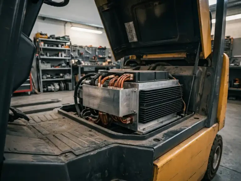
A motor controller regulates the speed, torque, and direction of an electric motor by managing the flow of electrical power from a battery or power source to the motor. It acts as the interface between operator input and motor output, translating signals from throttles, sensors, and control systems into precise electrical commands the motor can act on. Motor control of this kind is used in electric vehicles, industrial vehicles, and machinery, and a DC motor controller is the most common solution for battery-powered drives. This guide explains how a motor controller works, how AC and DC controllers differ, which protection functions matter, and what to look for when choosing one.
In battery-driven vehicles and industrial equipment, the motor controller determines how efficiently and safely that power is used. Without it, a motor would either run at full power or not at all. The sections below cover how that control works in practice, from the fundamentals of speed and torque regulation to what happens when a controller is commissioned on a new vehicle.
Need a controller for your application?
From traction to pump control, ask us about the right solution for your requirements.
How Does a Motor Controller Work?
A motor controller works by turning an operator command into switched battery current, then checking the result against sensor feedback. The signal and power chain follows the same basic sequence in most drive systems, from a forklift traction drive to a pump motor.
- The operator or a higher-level system gives a command, for example through a throttle, pedal, joystick, or a command signal over the network.
- The control logic or microcontroller reads that command and compares it with the current state of the drive.
- The logic calculates how much voltage, current, or frequency the motor needs and sends switching signals to the power stage.
- The power stage switches current from the battery to the motor, typically at high frequency.
- The motor turns and delivers torque to the wheels, pump, or other load.
- Current, speed, or position sensors report back to the control logic, which corrects its output in a continuous loop.
Each of the three core variables is influenced in a different way. Speed is set mainly through the voltage or duty cycle applied to the motor. Torque is limited and shaped by the current the controller allows. Direction is changed by reversing polarity, usually through H-bridge switching in a DC motor drive or by changing the phase sequence in an AC drive. This DC current control is what makes smooth starts, precise low-speed handling, and controlled reversing possible.
In closed-loop control, the sensor feedback is used to hold the requested value even when the load changes. Open-loop control sends a fixed command without checking the result. It is simpler, but less accurate, which is why most industrial vehicles use closed-loop motor drive systems.
How does a motor controller regulate speed and torque?
A motor controller regulates speed and torque by varying the voltage and current delivered to the motor, typically using a technique called pulse-width modulation (PWM). PWM switches the power supply on and off at high frequency, and by adjusting how long the signal stays on relative to off, the controller effectively controls the average power reaching the motor without wasting energy as heat across a resistor.
Torque control and speed control are closely related but distinct. Torque is determined by current: the more current flows through the motor windings, the greater the rotational force produced. Speed, on the other hand, depends on voltage. The controller manages both by continuously reading feedback from motor sensors and adjusting its output accordingly.
In closed-loop control systems, the controller compares actual motor speed or torque against the requested value and corrects any deviation in real time. This is what allows a forklift to maintain a steady lift speed under varying load, or an automated guided vehicle (AGV) to hold a precise travel speed on a slope. Open-loop control is simpler but less accurate, since it sends a fixed command without checking what the motor actually does in response.
What’s the difference between AC and DC motor controllers?
The core difference between AC and DC motor controllers is the type of motor they are designed to drive and the power conversion method they use. DC controllers manage direct current motors by varying the DC voltage or current delivered to the motor. AC controllers, often called inverters, convert DC battery power into variable-frequency AC to drive AC induction or permanent magnet motors.
DC motor controllers are generally simpler in design and have been used in electric vehicles for decades. They work well with series-wound or shunt-wound DC motors and are straightforward to commission. Their limitation is that brushed DC motors require physical commutators and brushes, which wear over time and need periodic replacement.
AC controllers are more complex because they must generate a three-phase AC waveform from a DC source, but the motors they drive are brushless and require less mechanical maintenance. AC induction motors and permanent magnet AC (PMAC) motors, including both surface-mounted (PMS) and interior permanent magnet (IPM) types, offer higher efficiency and better power density. This is why most modern electric industrial vehicles have moved toward AC drive systems.
The control algorithms also differ significantly. AC controllers must manage motor flux, slip frequency, and rotor position, often using vector control or field-oriented control (FOC) techniques. These approaches allow precise, independent control of torque and speed, which is particularly valuable in demanding applications like traction drives and hydraulic pump motors.
AC vs. DC Motor Controllers: Comparison Table
The table below summarizes how DC motor controllers and AC motor controllers (inverters) compare. It is a general guide, since the exact values depend on the specific motor and application.
| Criterion | DC motor controller | AC motor controller (inverter/VFD) |
|---|---|---|
| Motor type served | Brushed DC motors | Induction motors, PMSM, and BLDC motors (with a suitable drive) |
| Control method | PWM chopper | Field-oriented control, V/Hz control, inverter output |
| Complexity | Lower | Higher |
| Typical cost level | Generally lower for the controller, higher maintenance cost over time | Generally higher for the controller, lower maintenance cost over time |
| Efficiency | Good, limited by brush and commutator losses | Higher, especially with permanent magnet motors |
| Maintenance | Brushes and commutator need periodic service | Brushless motors need little mechanical maintenance |
| Typical applications | Forklifts, floor cleaning machines, utility vehicles | AGVs, conveyors, pumps, modern forklifts, traction drives |
DC controllers suit battery-powered vehicles where a simple, proven drive is enough. They convert battery voltage into a controlled DC output for brushed motors and are easy to set up and service.
AC controllers and frequency inverters suit applications that need higher efficiency, low motor maintenance, or precise torque control. They generate a variable three-phase output from the DC supply and drive brushless motors.
As a rule, DC controllers are chosen for simpler, cost-sensitive drives, while AC controllers are chosen where efficiency, durability, and control precision matter more.
What signals does a motor controller take as inputs?
A motor controller takes inputs from operator controls, motor sensors, and the vehicle or machine’s broader electrical system. The most immediate input is typically a throttle or speed reference signal, often a 0-5V analog voltage or a potentiometer output, which tells the controller how much torque or speed the operator is requesting.
Beyond the throttle, a controller receives several other categories of input:
- Motor feedback signals: Encoder pulses, resolver signals, or Hall effect sensor outputs that report actual rotor position and speed back to the controller in real time.
- Temperature signals: Thermistors or thermocouples mounted on the motor and the controller itself, used to prevent thermal overload.
- Digital logic inputs: Signals from key switches, direction switches, seat sensors, interlock circuits, and emergency stop buttons that determine whether the controller is allowed to run.
- Battery voltage and current: Measured directly by the controller to monitor state of charge, apply current limits, and protect the battery from excessive discharge rates.
- CAN bus messages: On modern systems, many of these signals arrive over a Controller Area Network (CAN bus) rather than as individual wired inputs, allowing the controller to communicate with a vehicle management system, display units, or other controllers.
The way a controller processes these inputs determines how responsive and safe the drive system is. Controllers that support CAN-based communication offer significant flexibility in how the machine is configured and monitored, since parameters and real-time data can be exchanged digitally rather than through hardwired analog signals alone.
How does a motor controller protect the motor and battery?
A motor controller protects both the motor and the battery by continuously monitoring operating conditions and applying limits or shutdowns when values exceed safe thresholds. This protection is built into the controller’s firmware and operates automatically, without requiring any action from the operator.
On the motor side, the controller watches for overcurrent conditions that could overheat the windings, and it monitors motor temperature directly when a temperature sensor is connected. If the motor runs too hot, the controller reduces current output to allow it to cool rather than cutting power abruptly, which would be disruptive in a traction application.
Battery protection follows a similar logic. The controller enforces maximum discharge current limits to prevent the battery from being drawn down faster than its chemistry can safely handle. It also monitors battery voltage and reduces output as voltage drops toward the lower cutoff threshold, protecting lithium or lead-acid cells from deep discharge damage. Some controllers apply regenerative braking, which returns energy to the battery during deceleration and helps extend the usable range of the vehicle.
Additional protections typically include undervoltage lockout (the controller refuses to start if battery voltage is too low), overvoltage protection (relevant during regenerative braking), short-circuit protection, and thermal protection of the controller’s own power switching devices. In safety-critical applications, the controller may also monitor for sensor faults or communication dropouts and respond with a controlled stop.
Which Protection Functions Does a Motor Controller Have?
A motor controller combines five dedicated protection functions: overcurrent and short-circuit protection, overtemperature protection, undervoltage and overvoltage protection, reverse polarity protection, and fault diagnostics with safe shutdown. Each one detects a specific fault condition and triggers a defined reaction.
Overcurrent and Short-Circuit Protection
This function is triggered when motor or battery current rises above the permitted limit, for example through a stalled motor, a mechanical overload, or a wiring fault. The controller first limits the current. If the fault persists or a short circuit is detected, it shuts down the power stage within microseconds. This protects the motor windings, the power stage, and the battery.
Overtemperature Protection
Temperature sensors on the power stage and the motor report heat build-up to the controller. When a threshold is reached, the controller reduces output current in a controlled way, known as thermal derating, and shuts down if the temperature keeps rising. This protects the motor insulation and the power semiconductors, and it avoids sudden power loss for the operator.
Undervoltage and Overvoltage Protection
The controller monitors the supply voltage continuously. A low battery voltage leads to reduced output or a lockout, which protects the cells from deep discharge. A voltage spike, for example during regenerative braking, leads to a reduction of regenerative current or a shutdown. This protects the battery, the controller electronics, and connected components.
Reverse Polarity Protection
If the battery is connected the wrong way round, the controller blocks the current path so that no damaging current can flow. This is typically solved with protection components in the power input. It protects the power stage and the electronics, and it also protects the technician during installation and service.
Fault Diagnostics and Safe Shutdown
The controller detects faults such as sensor failures, communication dropouts, or implausible signals. It reacts with an error code, a limited operating mode, or a controlled stop, depending on the severity. This protects the operator and the machine and makes troubleshooting faster for maintenance staff.
These functions matter most for industrial and electric vehicles operating under heavy loads, where overloads, heat, and voltage fluctuations are part of daily operation.
Motor Controllers in Electric and Industrial Vehicles
The requirements placed on a motor controller differ by vehicle type. The following applications show what each one typically demands from the drive.
Forklifts and Material Handling
In forklifts, the controller manages traction and hydraulic pump motors. Its job is smooth acceleration, stable speed under changing loads, and precise lift control. The main requirements are robustness, high current capability, and diagnostics that help keep the truck available.
Floor Cleaning Machines and Utility Vehicles
These machines work at low speeds, often in tight spaces and with frequent starts and stops. The controller provides precise low-speed control and gentle braking. The main requirements are reliable operation in dust and moisture and long runtime from the battery.
AGVs and Mobile Robots
Automated guided vehicles (AGVs) and mobile robots depend on exact speed and position control. The controller follows commands from the vehicle control system, usually over CAN, and holds the requested speed on slopes and with varying payloads. The main requirements are precise closed-loop control, reliable communication, and safety functions.
Electric Vehicles and Light Mobility
In electric vehicles and light mobility applications, the controller must deliver responsive acceleration and efficient use of the battery. Regenerative braking plays a key role here: during deceleration, the motor acts as a generator and the controller feeds the recovered energy back into the battery, which extends range. The main requirements are efficiency, compact design, and dependable protection functions.
What happens during motor controller commissioning?
Motor controller commissioning is the process of configuring and tuning the controller to work correctly with a specific motor, vehicle, and application. It typically involves setting motor parameters, calibrating input signals, configuring protection limits, and verifying that the drive system behaves as expected under real operating conditions.
The exact steps depend on the controller and motor type, but the general sequence runs as follows:
- Enter the motor’s nameplate data, including rated voltage, current, frequency, and pole count, into the controller’s configuration software.
- Run an automated motor identification or autotuning routine, which measures the motor’s electrical characteristics (resistance, inductance, flux) and stores them as control parameters.
- Calibrate the throttle and any other analog inputs so the controller correctly maps the physical signal range to the intended speed or torque range.
- Set protection thresholds for current limits, temperature limits, and battery voltage cutoffs appropriate to the application.
- Verify sensor operation, checking that encoder or Hall effect feedback signals are clean and correctly phased.
- Perform a test drive or operational test, checking for smooth acceleration, correct direction, stable speed holding, and proper response to safety inputs.
On older or simpler controllers, this process required manual parameter entry and a good deal of trial and error. Autotuning routines have changed that significantly: the controller runs the motor through a controlled test sequence and calculates the correct parameters automatically, which reduces commissioning time and removes much of the guesswork, particularly when working with unfamiliar motors.
How the SuperSigma2 handles motor control in demanding applications
The SuperSigma2 is DMC’s AC motor controller range for industrial electric vehicles. It addresses the practical challenges covered in this article through a combination of hardware design and software capability.
- The controller supports AC induction, PMS, and IPM motor types within a single platform, so the same hardware can be deployed across a wide range of vehicles without switching controller families.
- Fully automated motor and sensor tuning handles the commissioning process described above, identifying motor parameters without manual calculation and reducing setup time significantly in the field.
- Operating across 24V to 108V nominal battery voltage with nominal power up to 30 kW and peak power up to 60 kW, the SuperSigma2 covers applications from light AGVs through to forklifts and boom lifts.
- DMC’s proprietary IMS (Insulated Metal Substrate) technology mounts power switching devices directly onto a metal PCB, improving heat dissipation and keeping the controller running cooler under sustained load.
- Full CANopen support, introduced alongside the dual-processor architecture, allows the controller to integrate cleanly into modern vehicle networks and communicate with fleet management, display units, and safety systems.
How to Choose the Right Motor Controller
Choosing a motor controller starts with the motor and the application: motor type, supply voltage, current demand, and operating environment define which controllers are suitable. The following checklist covers the criteria that matter most:
- Motor type and rated power: brushed DC, BLDC, induction, or PMSM, and the continuous power the motor requires.
- Battery or supply voltage: the nominal voltage range the controller must handle.
- Continuous versus peak current: the current needed for steady operation and for short peaks such as acceleration or lifting.
- Control interface: analog inputs, CAN bus, or other digital communication.
- Required functions: regenerative braking, speed or torque mode, and diagnostics.
- Operating environment: temperature range, dust, moisture, and vibration.
- Certification and safety requirements: the standards and safety functions your vehicle or machine must meet.
DMC offers expertise in DC and AC motor controllers for industrial vehicles and machinery. If you are specifying or commissioning a controller for an electric vehicle or industrial platform, the DMC product range covers a broad set of configurations. Engineers can describe their application and contact the DMC team to get a recommendation and technical support.
Key Terms in Motor Control
- PWM: Pulse-width modulation, a method of controlling average power by switching the supply on and off at high frequency.
- Duty cycle: The share of each switching period during which the signal is on, usually given as a percentage.
- MOSFET: Metal-oxide-semiconductor field-effect transistor, a fast-switching power transistor commonly used in the power stage of low-voltage motor controllers.
- IGBT: Insulated-gate bipolar transistor, a power semiconductor used for switching higher voltages and currents in motor drives.
- H-bridge: A circuit of four switches that lets the controller reverse the current direction through a motor.
- Regenerative braking: A braking method in which the motor acts as a generator and returns energy to the battery.
- Field-oriented control (FOC): A vector control method that controls torque and flux of an AC motor independently.
- CAN bus: Controller Area Network, a robust serial communication network used to exchange signals between controllers, displays, and vehicle systems.
- AGV: Automated guided vehicle, a driverless vehicle that follows commands from a control system to transport loads.
Related Articles
- What happens if you run a motor in field weakening for too long?
- How do steering and traction systems interact in a battery-powered vehicle?
- How does machine mass influence traction-system behaviour?
- Can you manually tune a motor controller without a PC?
- What technical specifications actually determine motor controller performance?