
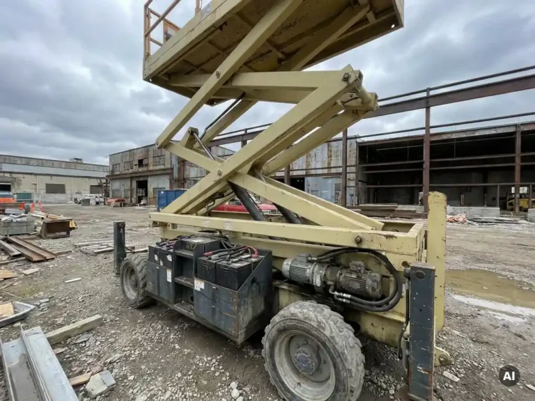
In an aerial work platform, the battery must supply power to several competing electrical systems simultaneously. The main consumers are the traction motor, the hydraulic pump motor for lifting and levelling functions, power steering, and a range of auxiliary loads including lighting, controls, and safety systems. Understanding how these loads interact is essential for OEM engineers designing reliable, efficient AWP power systems.
Which systems draw the most power from an AWP battery?
The two dominant power consumers in an electric aerial work platform are the hydraulic pump motor and the traction motor. Together they account for the majority of battery draw during normal operation. The pump motor typically demands the highest instantaneous current, particularly during lifting cycles, while the traction motor draws sustained power during travel across a job site.
Beyond these two primary loads, the battery also supplies power steering (where fitted), control electronics, operator displays, safety interlocks, lighting, and any platform-level auxiliary systems. Each of these loads may seem modest in isolation, but they draw continuously throughout the working shift, reducing the energy available for traction and lift. In a boom lift or scissor lift operating across an extended shift, the cumulative effect of auxiliary loads on battery runtime is significant.
The challenge for OEM engineers is not simply sizing the battery to meet peak demand, but managing the way competing loads interact when multiple systems activate at the same time.
How does the traction motor compete with the lift pump motor?
The traction motor and the hydraulic pump motor compete directly for battery power because they can both activate simultaneously. In practice, many AWP control systems prevent full simultaneous operation through interlocks, but partial overlap still occurs, and the combined current draw during those moments can stress both the battery and the motor controllers.
The traction motor in a scissor lift or boom lift is typically sized for moderate continuous power but must handle short bursts of high current when accelerating across uneven ground. The pump motor, by contrast, is sized for the peak hydraulic demand during lifting, which can represent the highest single load event in the entire machine cycle. When a platform is raised while the machine is repositioning, the battery must supply power to both simultaneously.
This competition has direct consequences for battery voltage. Under combined load, terminal voltage can sag significantly, and if the motor controllers are not designed to manage this gracefully, performance degrades or protection cutouts activate. Engineers designing AWP drivetrains need to account for worst-case simultaneous demand, not just individual load peaks.
What role does power steering play in AWP power consumption?
Power steering in an electric aerial work platform adds a continuous or semi-continuous electrical load that runs independently of the main traction and lift functions. In machines that use electro-hydraulic power steering, a dedicated pump motor runs whenever the steering system is active. In machines with electric power-assisted steering, the load is lower but still present during every steering input.
The power demand from steering is smaller than that of the traction or pump motor, but it draws from the same battery throughout the working shift. In applications where the machine repositions frequently, such as indoor AGV-style platforms or boom lifts navigating congested sites, the steering load accumulates meaningfully over time. Engineers sometimes underestimate this contribution when calculating overall energy budgets, particularly on machines with large platform heights where frequent fine repositioning is needed.
How do auxiliary loads affect overall battery runtime?
Auxiliary loads reduce AWP battery runtime by drawing power continuously, regardless of whether the machine is actively lifting or travelling. These loads include the operator control panel, safety relay circuits, CAN bus communications, platform lighting, horn circuits, and any telematics or fleet management hardware fitted to the machine.
Individually, each auxiliary load is small. A control panel and display might draw a few tens of watts; lighting and safety circuits add more. But these loads run for the entire shift, which means they consume a disproportionate share of battery energy relative to their peak power demand. On a machine operating a ten-hour shift with moderate utilisation of the main functions, auxiliary loads can account for a meaningful fraction of total energy consumed.
The practical implication is that battery sizing calculations should never focus exclusively on traction and lift peak power. A complete energy budget must include the continuous baseline draw from all auxiliary systems, multiplied by the expected shift duration. Ignoring this leads to shorter-than-expected runtime in the field, which is a common source of customer dissatisfaction in AWP deployments.
How does a motor controller help manage competing electrical loads?
A motor controller manages competing electrical loads by regulating how much current each motor draws at any given moment, protecting the battery from excessive discharge events and maintaining system stability when multiple loads are active. The controller achieves this through current limiting, torque limiting, and regenerative braking, all of which reduce net battery draw during demanding operating conditions.
In an AWP with separate controllers for the traction motor and the pump motor, coordinated current management is particularly important. If both controllers demand peak current simultaneously, the battery voltage sag can trigger protection cutouts across the system. Controllers that communicate over a shared bus, such as CANopen, can coordinate their current demands and implement load prioritisation strategies that keep the system operating smoothly.
Regenerative braking is another mechanism through which the traction controller reduces net energy consumption. When the machine decelerates, the traction motor acts as a generator, returning energy to the battery. In frequent stop-start applications typical of AWP work, this recovery meaningfully extends runtime. The effectiveness of regeneration depends on the controller’s ability to manage the returned current without overcharging the battery, which requires close integration between the controller and the battery management system.
You can explore the range of motor controllers for electric vehicles to understand how controller architecture influences system-level power management.
What should OEM engineers consider when sizing an AWP power system?
OEM engineers sizing an AWP power system need to work from a complete energy budget that accounts for all electrical loads across a realistic duty cycle, not just the peak demands of individual motors. The key inputs are the continuous power draw of auxiliary loads, the frequency and duration of lift cycles, the traction duty profile, and any simultaneous load events that the machine’s interlocks do not fully prevent.
Battery voltage selection has a direct effect on system efficiency. Higher nominal voltages reduce the current required to deliver the same power, which reduces resistive losses in cabling and switching devices and extends battery runtime. For AWPs with total installed motor power above a few kilowatts, operating at 48 V or above is generally more efficient than lower-voltage architectures.
Thermal management of the motor controllers is also a sizing consideration that affects long-term reliability. Controllers that run hot under sustained load reduce their own efficiency and can enter thermal derating modes that limit available power at exactly the moments when it is most needed. Specifying controllers with effective heat dissipation built into their architecture removes this as a variable in the field.
Finally, engineers should consider the controller’s ability to support different motor types within the same platform. AWPs often use different motor technologies for traction and hydraulic pump functions, and a controller architecture that supports AC induction, PMS, and IPM motors from a single hardware platform simplifies inventory, reduces qualification effort, and gives more flexibility when motor suppliers change.
How the SuperSigma2 addresses AWP power management
DMC’s SuperSigma2 controller range is designed specifically for the kind of multi-load power management that AWP applications demand. Key capabilities relevant to aerial work platform engineers include:
- Operation across 24 V to 108 V nominal battery voltages, covering the full range of AWP architectures from compact scissor lifts to large boom lifts
- Nominal power up to 30 kW and peak power up to 60 kW, providing headroom for simultaneous traction and pump motor demand events
- Support for AC induction, PMS, and IPM motor types within a single controller platform, allowing engineers to use the same hardware for both traction and hydraulic pump applications
- Fully automatic motor and sensor tuning, which reduces commissioning time and eliminates manual calibration errors when deploying across multiple machine variants
- CANopen communication (standard since early 2023), enabling coordinated load management between traction and pump controllers across the machine’s CAN network
- IMS (Insulated Metal Substrate) thermal architecture, which keeps power switching devices cooler under sustained load and eliminates thermal derating during extended duty cycles
For OEM engineers working on AWP power system design, the SuperSigma2’s combination of broad voltage range, multi-motor-type support, and integrated thermal management addresses the most common sources of field performance problems. To discuss your specific application requirements, contact the DMC engineering team directly.
Related Articles
- How does operating on a slope affect an electric aerial work platform?
- Why can steering require high torque even at very low vehicle speed?
- What makes the SuperSigma2 different from earlier DMC controller ranges?
- PMSM vs PMS motor controller: is there actually a difference?
- What technical specifications actually determine motor controller performance?