
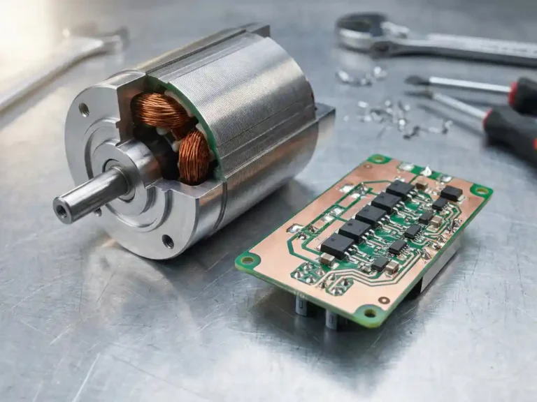
Motor controllers are not all built the same, and the differences between them go well beyond marketing language. Two controllers can both regulate speed using pulse-width modulation (PWM) at the hardware level, yet produce dramatically different results in efficiency, torque response, and thermal behavior. The distinction that matters most in demanding electric vehicle and industrial applications is whether the controller implements field oriented control (FOC) or relies on a more conventional PWM switching strategy. Understanding what separates these two approaches helps engineers and system designers make better decisions when specifying an electric vehicle controller for a given application.
What Is FOC (Field Oriented Control) in Electronics?
FOC, or Field Oriented Control (also called vector control), is a method of driving AC and brushless motors by independently controlling the magnetic flux and the torque of the motor. Instead of simply adjusting voltage, a FOC motor controller regulates exactly how much of the stator current builds the magnetic field and how much produces useful rotation.
In plain language, the controller measures the phase currents flowing into the motor and converts them with two mathematical steps, the Clarke and Park transforms, into a rotating reference frame that moves along with the rotor. In that frame, the three alternating phase currents become two DC-like values that are easy to regulate: the d-axis current, which controls flux, and the q-axis current, which controls torque. Two independent control loops then adjust these values, and the result is transformed back into phase voltages for the inverter.
When people search for “foc electrical” or “foc motor”, they are referring to this same control approach. A FOC motor is simply a motor, typically a BLDC (brushless DC), PMSM (permanent magnet synchronous motor), or AC induction machine, driven by a controller that uses this algorithm. The key idea is that torque is controlled directly and continuously, rather than indirectly through voltage or speed alone.
How PWM control works at the motor level
Pulse-width modulation (PWM) is the foundational switching technique used in virtually all modern motor drives. The controller rapidly switches power transistors on and off, varying the duty cycle to control the average voltage applied to the motor windings. At high switching frequencies, the motor’s own inductance smooths the resulting current into something close to a sine wave.
In a basic PWM controller, the control loop typically regulates voltage or total current without precise knowledge of the motor’s internal magnetic state. The controller knows how fast the motor is spinning and adjusts the output accordingly, but it does not continuously track where the rotor is positioned relative to the stator’s magnetic field. This open-loop or loosely closed-loop approach is straightforward to implement and works acceptably for many constant-load applications, but it leaves torque production less than optimal across varying speed and load conditions.
The core mechanics of field oriented control
Field oriented control (FOC), sometimes called vector control, takes a fundamentally different approach from basic PWM speed control. Rather than simply controlling voltage or total current, an FOC motor controller decomposes the stator current into two orthogonal components: one that produces magnetic flux and one that produces torque. By controlling these two components independently, the drive can maintain optimal alignment between the stator field and the rotor at all times.
This requires continuous knowledge of rotor position, achieved either through physical sensors or through mathematical observers running in real time. The controller uses coordinate transformations to convert measured phase currents into a rotating reference frame aligned with the rotor flux, applies independent PI (proportional-integral) regulators to each current component, then transforms the output back into phase voltages for the PWM stage. The result is precise, instantaneous control over torque rather than indirect control through voltage or speed alone.
For AC induction motors and PMAC (permanent magnet AC) motors, including both surface-mounted permanent magnet (SPM) and interior permanent magnet (IPM) types, FOC allows the controller to account for the motor’s electrical characteristics dynamically, rather than relying on fixed assumptions baked in at commissioning.
What Is the Difference Between FOC Control and Traditional Motor Control Systems?
The difference between FOC and traditional motor control is the control algorithm: traditional control, such as trapezoidal or six-step commutation and simple PWM speed control, switches the motor phases in fixed steps based on rotor position sectors. FOC instead continuously shapes sinusoidal phase currents so that the stator field stays at an optimal angle to the rotor field. The practical outcome is smoother torque, better efficiency, and more precise control, at the price of more computation and more complex firmware.
| Criteria | FOC Motor Controller | Traditional PWM / Six-Step Control |
|---|---|---|
| Torque smoothness | Low torque ripple, smooth rotation | Noticeable torque ripple at each commutation step |
| Torque precision | Direct control of torque via the q-axis current | Indirect control through voltage or total current |
| Efficiency | High across the load range, especially at partial load | Lower at partial load and during speed transitions |
| Acoustic noise | Quiet operation with sinusoidal currents | More audible noise and vibration |
| Low-speed performance | Smooth, controllable torque at low speed | Prone to cogging and uneven torque |
| Dynamic response | Fast response to load and torque changes | Slower response, often limited by conservative ramp rates |
| Processing power required | Higher, needs a capable microcontroller or DSP | Low, runs on simple hardware |
| Cost and complexity | Higher development and tuning effort | Lower cost, simple to implement |
It is worth clarifying that FOC still uses PWM at the hardware level. Both approaches switch the same kind of power transistors with the same kind of modulation, so the real difference lies in the control algorithm that decides what to switch and when. This is why two controllers with similar power stages can behave so differently in practice.
Why FOC Delivers Better Torque Precision and Efficiency
FOC delivers better torque precision and efficiency than traditional PWM control because it regulates torque directly through the q-axis current and keeps the stator current aligned with the rotor field, which maximizes torque per amp. The two subsections below cover torque behavior and energy and thermal behavior in turn.
Torque Precision and Smooth Operation
Because FOC controls torque directly through the q-axis current, the drive can produce exactly the torque requested without the side effects of indirect control. The separation of flux and torque current components gives the drive the ability to respond to torque demands almost instantaneously. When a forklift suddenly picks up a load or an AGV (automated guided vehicle) changes direction, the controller can ramp torque without the lag associated with waiting for flux to build or decay.
Conventional PWM drives often compensate for slower dynamic response by applying aggressive current limits or using conservative ramp rates, which protects the motor but at the cost of responsiveness. An FOC controller can apply maximum available torque within the motor’s thermal limits from the very first electrical cycle, which is particularly valuable in applications that require precise positioning, smooth acceleration, or rapid load handling. The difference is most noticeable at low speeds, where scalar control tends to produce cogging or uneven torque delivery.
- Low torque ripple for smooth rotation
- Stable, controllable rotation at low speed
- Fast response to sudden load changes
- Accurate torque limiting for protecting mechanics and the motor
- Reduced vibration and mechanical stress in the drivetrain
Energy Efficiency and Thermal Benefits
One of the most tangible benefits of FOC is improved efficiency across the operating range. Because the controller maintains optimal current alignment at all times, it delivers maximum torque per amp, so less energy is wasted as heat in the motor windings. In a conventional scalar-controlled drive, the motor often draws more current than necessary to produce a given torque, particularly at partial loads or during speed transitions.
Reduced motor losses translate directly into lower winding temperatures and extended motor life. On the controller side, more accurate current control means the power switching devices operate more predictably, which reduces switching losses and makes thermal management more straightforward. In battery-driven vehicles, where every percentage point of efficiency affects range and battery cycle life, these gains accumulate meaningfully over a full duty cycle. The gains are typically most visible at partial load, where a typical FOC motor driver avoids drawing surplus current.
- Lower copper losses thanks to maximum torque per amp
- Reduced motor heating and longer winding life
- Better efficiency at partial load and during speed changes
- Extended runtime and battery life in battery-powered systems
- Simpler thermal management for FOC controllers under sustained duty
What Is a FOC Motor Driver and What Is Inside a FOC Controller?
A FOC motor driver is an electronic unit that combines a power stage with a control stage to run a motor using the field oriented control algorithm. The power stage is the inverter, built from MOSFETs or IGBTs (insulated-gate bipolar transistors) and their gate drivers, which switch the battery or DC bus voltage onto the motor phases. The control stage is the microcontroller or DSP (digital signal processor) that runs the FOC algorithm, reads the sensors, and generates the switching commands.
A complete FOC controller typically includes the following core elements:
- Current sensing on the motor phases to feed the control loops
- A position feedback input for an encoder, resolver, or Hall sensors, or an observer for sensorless operation
- PWM generation to drive the inverter switches
- Protection functions such as overcurrent, overvoltage, and thermal shutdown
- Communication interfaces such as CAN (Controller Area Network) or UART (universal asynchronous receiver-transmitter) for integration with the vehicle or machine
The same PWM hardware can often run either six-step or FOC firmware. This reinforces the central point of the comparison above: the difference between the two approaches lies in the control algorithm, not in the existence of PWM switching itself.
Can FOC Run Sensorless, and What Is Automated Motor Tuning?
Yes. Modern FOC controllers can run sensorless by estimating rotor position from the motor’s back-EMF (back electromotive force) and electrical model, and they can identify motor parameters automatically. Sensorless operation retains most of the performance of sensored control above a minimum speed, while automated tuning removes manual commissioning work.
Early FOC implementations required a shaft encoder or resolver to determine rotor position, adding cost and a potential point of failure. Sensorless FOC removes that hardware by calculating rotor position mathematically, with the main limitation being reduced reliability at very low speeds and standstill.
Automated motor tuning takes this further. Rather than requiring a skilled engineer to manually characterize a motor’s resistance, inductance, and flux linkage before commissioning, advanced controllers can run an automated identification routine that measures these parameters directly. This not only reduces setup time but also ensures the control model accurately reflects the actual motor installed, rather than relying on datasheet values that may not match manufacturing tolerances. For fleet operators running multiple vehicle types, automated tuning significantly reduces the engineering burden of deploying new motor and controller combinations.
Which Controller Technology Fits Your EV or Industrial Application?
FOC is the better fit for applications with variable loads, frequent acceleration and deceleration, low-speed torque demands, or a need to maximize battery efficiency, while basic PWM or six-step control suits simple constant-speed applications. The right answer depends on the load profile, the required precision, the energy budget, and the available processing hardware.
Electric Vehicles and E-Mobility
In e-bikes, scooters, and traction drives, smooth torque, efficiency, and quiet operation directly affect the rider or operator experience and the achievable range. FOC becomes the better choice when the application involves variable loads, frequent acceleration and deceleration cycles, low-speed torque demands, or a need to maximize battery efficiency. Forklifts, stackers, scissor lifts, AGVs, and marine traction systems all benefit from the torque accuracy and efficiency that vector control provides.
Industrial Automation and Robotics
In servo drives, conveyors, pumps, fans, and robotics, precise speed and position control are often required, and torque must stay predictable under changing loads. A FOC motor controller delivers the dynamic response and accuracy these systems depend on. The operating voltage range and motor type also matter: FOC is available for both AC induction and PMAC motors, and a controller that supports both motor types gives system designers flexibility when sourcing motors or upgrading existing platforms.
When Traditional PWM Control Is Still Enough
Basic PWM or six-step control remains a cost-effective solution for simple, constant-speed applications with limited dynamic requirements, such as a fixed-speed pump or a fan with no precise speed regulation needs. In these cases the added computation and tuning effort of FOC brings little practical benefit, and a simpler controller keeps cost and complexity down.
Thermal management at the controller level should also factor into the decision. Even the most sophisticated control algorithm cannot compensate for a controller that runs too hot under sustained load, so the physical design of the power stage is as important as the software running on it.
A short checklist helps structure the decision:
- How precise does torque control need to be?
- What efficiency or range target must the system meet?
- What budget is available for hardware and development?
- Is a capable microcontroller or DSP available for the control algorithm?
- Are there noise or vibration limits to respect?
- Which motor type, AC induction, PMAC, or BLDC, is being used?
How DMC supports advanced motor control applications
DMC’s SuperSigma2 and Sigma2N controller ranges are built around field oriented control for both AC induction and PMAC motors, operating across nominal battery voltages from 24V to 108V and supporting peak powers up to 60kW. The controllers are designed specifically for the demands of battery-driven electric vehicles and industrial platforms, with the following capabilities built in as standard:
- Fully automated motor and sensor identification, removing the need for manual parameter entry at commissioning
- Sensorless motor control for applications where encoder installation is impractical or undesirable
- Proprietary IMS (Insulated Metal Substrate) technology that mounts power MOSFETs directly onto a metal PCB, keeping switching devices cooler under sustained load
- Flexible configurations covering single or dual traction, pump, and power-steering motor applications
- Custom solutions available for applications that fall outside standard product specifications
If you are evaluating controller options for a forklift, AGV, aerial work platform, or other electric vehicle application, the full product range covers a broad set of operating conditions. To discuss a specific application or request technical support, get in touch with the DMC team directly.
FOC Motor Controller FAQ
What does FOC stand for in motor control?
FOC stands for Field Oriented Control, also known as vector control. It is a method that regulates the flux and torque components of the motor current independently. This gives the controller direct command over the torque the motor produces.
Is FOC better than PWM control?
FOC is not an alternative to PWM, because a FOC controller still uses PWM to switch its power stage. The real comparison is between FOC and six-step or basic PWM speed control. FOC generally offers smoother torque, higher efficiency, and better dynamic response, while simpler control can be sufficient for basic applications.
Can FOC run without position sensors?
Yes, modern FOC controllers can run sensorless by estimating rotor position from the motor’s back-EMF and electrical model. Performance is typically very good above a minimum speed threshold. At very low speeds or standstill, a position sensor still gives more reliable results.
Does FOC need a more powerful processor?
Yes, FOC requires more processing power than six-step control because it performs coordinate transformations and runs fast current control loops in real time. A capable microcontroller or DSP is therefore standard in a FOC motor driver. Modern devices make this requirement easy to meet in most designs.
Which motors work with FOC controllers?
FOC works with BLDC motors, PMSM and PMAC motors, and AC induction motors. The controller must be configured for the motor type and match its voltage and current range. Controllers that support several motor types give designers more flexibility.
Is an FOC controller worth the extra cost?
For applications with variable loads, low-speed torque demands, or a need for high efficiency and quiet operation, an FOC controller is usually worth the extra cost. The savings in energy, heat, and mechanical wear often offset the higher initial price. For simple constant-speed uses, a basic controller may be the more economical choice.
Choosing the Right Motor Controller for Your Project
Choosing between FOC and traditional control comes down to what your application actually demands. FOC rewards you where smooth torque, efficiency, and precise control matter, while simpler control keeps costs low where requirements are modest. Matching the controller to the motor type, voltage, and current range is just as important as choosing the algorithm.
The main points to take away:
- FOC suits applications that demand smooth torque, efficiency, and precise control
- Traditional control suits simple, cost-sensitive uses with constant load
- Sensor choice affects low-speed performance, so consider sensored or sensorless operation carefully
- Match the controller to the motor type and to the required voltage and current range
- The real difference between the two approaches lies in the control algorithm, not in the use of PWM
If you would like help selecting a FOC motor controller for your project, you can contact DMC for guidance or browse the motor controller range to see what fits your requirements.
Related Articles
- What happens to an electric steering system during rapid direction changes?
- Why do mobile machines need high torque at low speed?
- Why does motor controller temperature affect long-term reliability?
- Manual motor tuning vs autotuning: what's actually different?
- What two types of circuits are we most likely to see in motor controllers?